Creating position of Joy Stick program using Arduino UNO
Required Components
- Arduino UNO -1 no
- Joystick Module -1 no
- LEDs -5 no
- Resistor: 150 ohm -5 no
- Breadboard -1 no
- Connecting wires -1 set
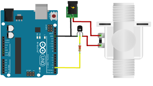
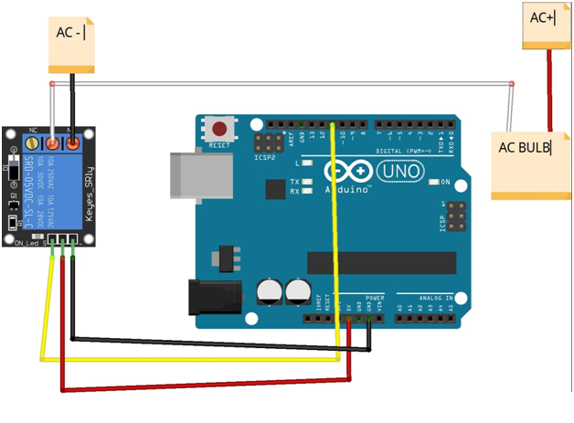
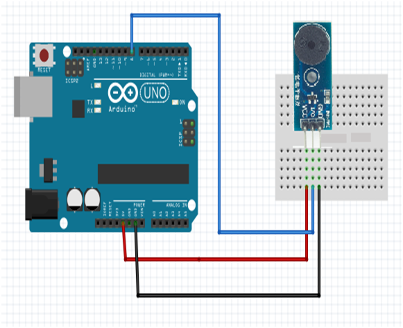
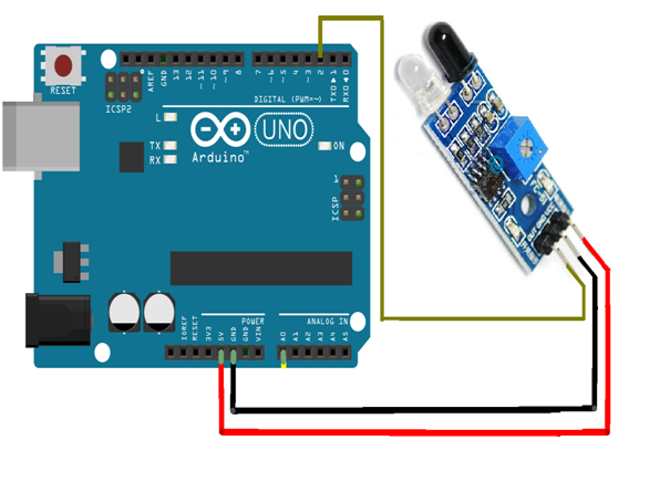
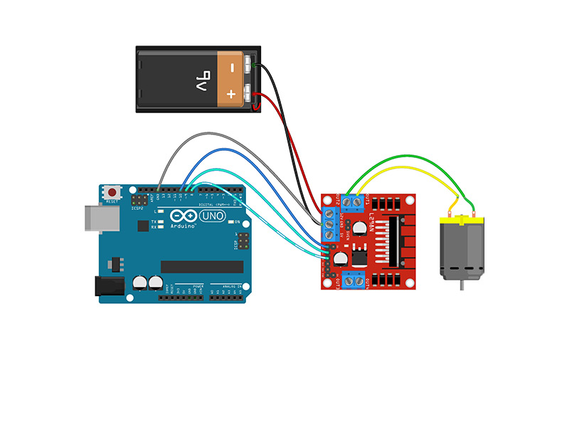
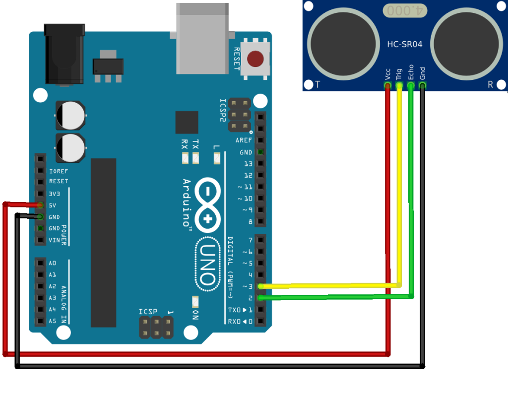
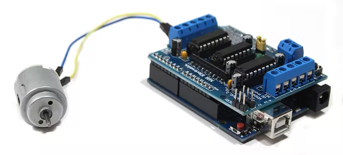
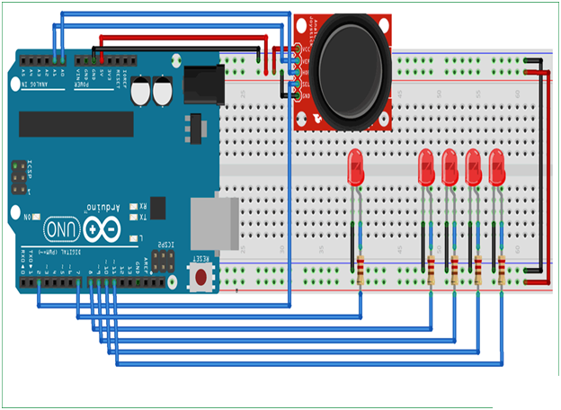
Circuit
Steps
- Make sure the components are working properly.
- Connect the 150 Ohm Resistor and Arduino Uno gnd to the LED.
- Connect the Arduino Uno Board 2nd pin to the Joy stick.
- Connect the Arduino Uno 8 ,9 ,10 ,11th pins to the Joy stick.
- Connect the Arduino Uno 5V & gnd to the Joy stick controller.
- Connect the Arduino Uno Board A0 & A1 pins to the X -axis & Y-axis.
- Check the Circuit Connections.
- Check the Arduino program.
- Run the Arduino program.
Arduino Program
int joyX=A0;
int joyY=A1;
int button=2;
int buttonState = 0;
int buttonState1 = 0;

void setup(  )
{
  pinMode(7,OUTPUT);
  pinMode(button,INPUT);
  digitalWrite(button, HIGH);
  Serial.begin(9600);
}

void loop(  )
{
  int xValue = analogRead(joyX);
  int yValue = analogRead(joyY);
  Serial.print(xValue);
  Serial.print("\t");
  Serial.println(yValue);

  buttonState = digitalRead(button);
  Serial.println(buttonState);
  if (xValue>=0 && yValue<=10)
  {
    digitalWrite(10, HIGH);
  }else
  {
    digitalWrite(10, LOW);
  }
  if (xValue<=10 && yValue>=500)
  {
    digitalWrite(11, HIGH);
  }else
  {
    digitalWrite(11, LOW);
  }
  if (xValue>=1020 && yValue>=500)
  {
    digitalWrite(9, HIGH);
  }else
  {
    digitalWrite(9, LOW);
   }
  if (xValue>=500 && yValue>=1020)
  {
    digitalWrite(8, HIGH);
  }else
  {
    digitalWrite(8, LOW);
  }
  if (xValue>=1020 && yValue>=1020)
  {
    digitalWrite(9, LOW);
    digitalWrite(8, LOW);
  }
  if (buttonState == LOW)
  {
    Serial.println("Switch = High");
    digitalWrite(7, HIGH);
  }else
  {
    digitalWrite(7, LOW);
  }
  buttonState1 = digitalRead(7);
  Serial.println(buttonState1);
  delay(100);
}
Usage
- Gaming controls
- Air craft