Raspberry Pi Pico வை பயன்படுத்தி 4×4 Matrix Keypad Module ஐ கட்டுப்படுத்துவது
Required Components
4×4 Matrix Keypad-1 no
Raspberry Pi Pico board-1 no
Data Cable-1 no
Connecting Wires-8 no
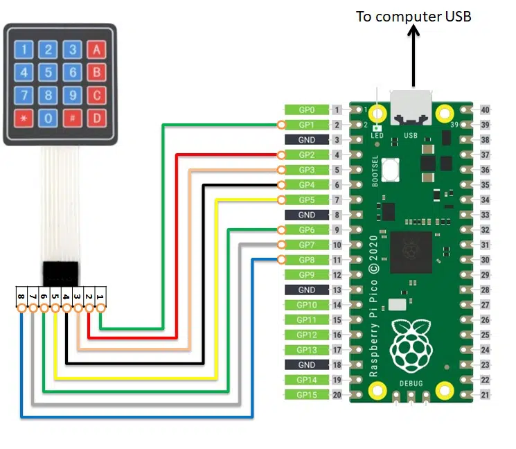
Circuit
Steps
நாம் பயன்படுத்தும் உபகரணங்கள் சரியாக வேலை செய்கிறதா என்பதை உறுதி செய்து கொள்ளவும்.
4×3 Matrix keypad 1 முதல் 8 வரை உள்ள பின்களை Raspberry Pi Pico GP1 முதல் GP8 வரை உள்ள பின்களுடன் இணைக்க வேண்டும்.
Python program ஐ சரி பார்க்க வேண்டும்.
மின்சுற்றை சரி பார்க்க வேண்டும்.
Python program ஐ ரன் செய்ய வேண்டும்.
Python Program
from machine import Pin
import utime

# define PINs according to cabling
# following array matches 1,2,3,4 PINs from 4x4 Keypad Matrix
col_list=[1,2,3,4]
# following array matches 5,6,7,8 PINs from 4x4 Keypad Matrix
row_list=[5,6,7,8]

# set row pins to output and change array elements from
#    int to Pin objects, all set to high
for x in range(0,4):
    row_list[x]=Pin(row_list[x], Pin.OUT)
    row_list[x].value(1)

# set columns pins to input and change array elements
#   from int to Pin objects. We'll read user input here
for x in range(0,4):
    col_list[x] = Pin(col_list[x], Pin.IN, Pin.PULL_UP)

# Create a map between keypad buttons and chars
key_map=[["D","#","0","*"],\
         ["C","9","8","7"],\
         ["B","6","5","4"],\
         ["A","3","2","1"]]

def Keypad4x4Read(cols,rows):
  for r in rows:
    r.value(0)
    result=[cols[0].value(),cols[1].value(),cols[2].value(),cols[3].value()]
    if min(result)==0:
      key=key_map[int(rows.index(r))][int(result.index(0))]
      r.value(1) # manages key keept pressed
      return(key)
    r.value(1)

# Start the main loop
print("--- Ready to get user inputs ---")
while True:
    key=Keypad4x4Read(col_list, row_list)
    if key != None:
      print("You pressed: "+key)
      utime.sleep(0.3) # gives user enoght time to release without having double inputs
Raspberry Pi Pico வை பயன்படுத்தி 4×3 Matrix Keypad Module ஐ கட்டுப்படுத்துவது
Required Components
4×3 Matrix Keypad-1 no
Raspberry Pi Pico board-1 no
Data Cable-1 no
Connecting Wires-8 no
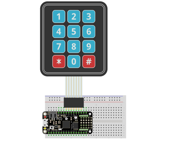
Circuit
Steps
நாம் பயன்படுத்தும் உபகரணங்கள் சரியாக வேலை செய்கிறதா என்பதை உறுதி செய்து கொள்ளவும்.
4×3 Matrix keypad 1 முதல் 7 வரை உள்ள பின்களை Raspberry Pi Pico GP1 முதல் GP7 வரை உள்ள பின்களுடன் இணைக்க வேண்டும்.
Python program ஐ சரி பார்க்க வேண்டும்.
மின்சுற்றை சரி பார்க்க வேண்டும்.
Python program ஐ ரன் செய்ய வேண்டும்.
Python Program
from machine import Pin
import utime

# define PINs according to cabling
# following array matches 1,2,3 PINs from 3x4 Keypad Matrix
col_list=[1,2,3]
# following array matches 4,5,6,7 PINs from 3x4 Keypad Matrix
row_list=[4,5,6,7]

# set row pins to output and change array elements from
#    int to Pin objects, all set to high
for x in range(0,4):
    row_list[x]=Pin(row_list[x], Pin.OUT)
    row_list[x].value(1)

# set columns pins to input and change array elements
#   from int to Pin objects. We'll read user input here
for x in range(0,3):
    col_list[x] = Pin(col_list[x], Pin.IN, Pin.PULL_UP)

# Create a map between keypad buttons and chars
key_map=[["#","0","*"],\
         ["9","8","7"],\
         ["6","5","4"],\
         ["3","2","1"]]

def Keypad3x4Read(cols,rows):
  for r in rows:
    r.value(0)
    result=[cols[0].value(),cols[1].value(),cols[2].value()]
    if min(result)==0:
      key=key_map[int(rows.index(r))][int(result.index(0))]
      r.value(1) # manages key keept pressed
      return(key)
    r.value(1)

# Start the main loop
print("--- Ready to get user inputs ---")
while True:
    key=Keypad3x4Read(col_list, row_list)
    if key != None:
      print("You pressed: "+key)
      utime.sleep(0.3) # gives user enoght time to release without having double inputs
L298N Motor Driver ஐ பயன்படுத்தி 2 DC மோட்டார்களை கட்டுப்படுத்துவது
Required Components
L298N Motor Driver Module-1 no
Raspberry Pi Pico-1 no
DC Motor(gear)-2 no
12V Battery-1 no
Data Cable-1 no
Connecting Wires-4 no
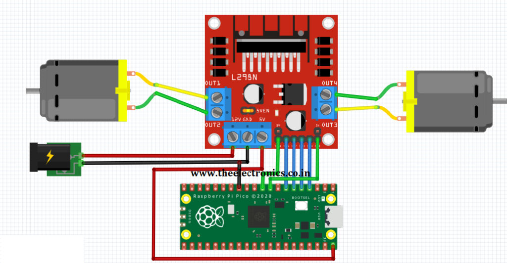
Circuit
Steps
நாம் பயன்படுத்தும் உபகரணங்கள் சரியாக வேலை செய்கிறதா என்பதை உறுதி செய்து கொள்ளவும்.
மோட்டார் Driver போர்டு உடன் +12V battery இணைக்க வேண்டும்.
+12V பேட்டரி இணைப்புகளை சரியாகவும் கவனமாகவும் இணைக்க வேண்டும்.
மோட்டார் Driver போர்டு ENA, IN1, IN2, IN3, IN4, ENB பின்களை Raspberry Pi Pico பின்களான GP6, GP5, GP4, GP3, GP2, GP7 உடன் இணைக்க வேண்டும்.
மோட்டார் Driver போர்டு OUTPUT பின்களை DC மோட்டார் பின்களுடன் இணைக்க வேண்டும்.
மோட்டார் Driver போர்டு GND ஐ Raspberry Pi Pico board GND உடன் இணைக்க வேண்டும்.
Python program ஐ சரி பார்க்க வேண்டும்.
மின்சுற்றை சரி பார்க்க வேண்டும்.
Python program ஐ ரன் செய்ய வேண்டும்.
Python Program
from machine import Pin
import utime

m1 = Pin(5, Pin.OUT)
m2 = Pin(4, Pin.OUT)
m3 = Pin(3, Pin.OUT)
m4 = Pin(2, Pin.OUT)

en1 = Pin(6, Pin.OUT)
en2 = Pin(7, Pin.OUT)

en1(1)  # motor 1 enable, set value 0 to disable
en2(1)  # motor 2 enable, set value 0 to disable

while True:
    #Both Motor in forward direction
    m1(1)
    m2(0)
    m3(1)
    m4(0)
    utime.sleep(1)
    #Both Motor in Reverse direction
    m1(0)
    m2(1)
    m3(0)
    m4(1)
    utime.sleep(1)
    #Both Motor in stop position
    m1(0)
    m2(0)
    m3(0)
    m4(0)
    utime.sleep(5)
L298N Motor Driver ஐ பயன்படுத்தி 1 DC மோட்டாரை கட்டுப்படுத்துவது
Required Components
L298N Motor Driver Module-1 no
Raspberry Pi Pico-1 no
DC Motor(gear)-2 no
12V Battery-1 no
Data Cable-1 no
Connecting Wires-4 no
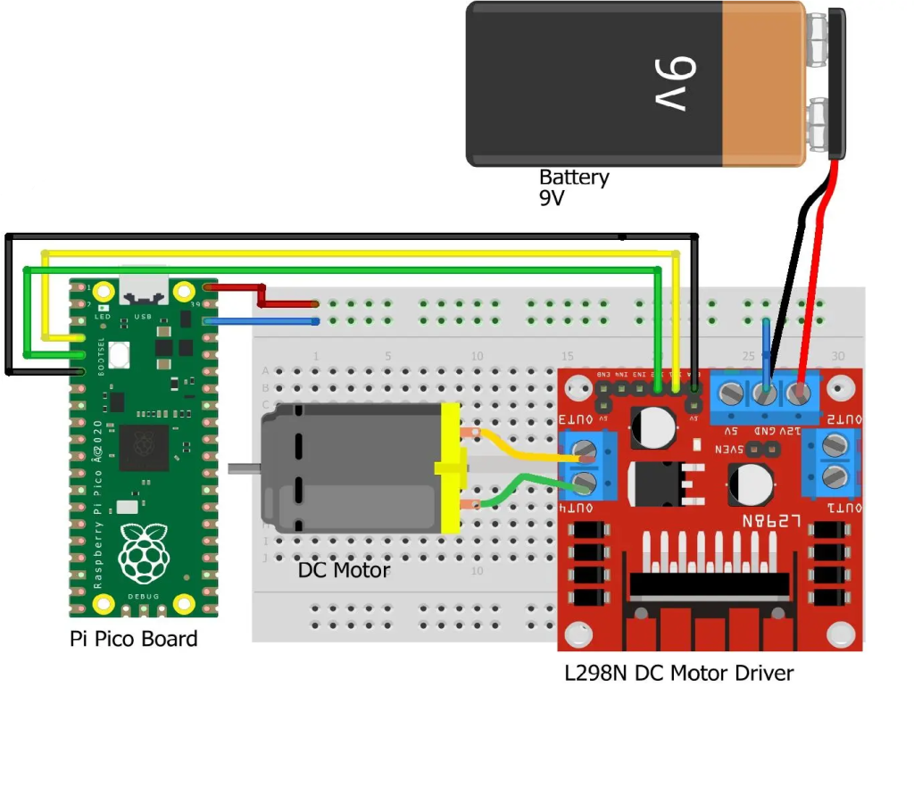
Circuit
Steps
நாம் பயன்படுத்தும் உபகரணங்கள் சரியாக வேலை செய்கிறதா என்பதை உறுதி செய்து கொள்ளவும்.
மோட்டார் Driver போர்டு உடன் +12V battery இணைக்க வேண்டும்.
+12V பேட்டரி இணைப்புகளை சரியாகவும் கவனமாகவும் இணைக்க வேண்டும்.
மோட்டார் Driver போர்டு ENA, IN1, IN2 பின்களை Raspberry Pi Pico பின்களான GP4, GP2, GP3 உடன் இணைக்க வேண்டும்.
மோட்டார் Driver போர்டு OUTPUT பின்களை DC மோட்டார் பின்களுடன் இணைக்க வேண்டும்.
மோட்டார் Driver போர்டு GND ஐ Raspberry Pi Pico GND உடன் இணைக்க வேண்டும்.
Python program ஐ சரி பார்க்க வேண்டும்.
மின்சுற்றை சரி பார்க்க வேண்டும்.
Python program ஐ ரன் செய்ய வேண்டும்.
Python Program
from machine import Pin
import utime

m1 = Pin(2, Pin.OUT)
m2 = Pin(3, Pin.OUT)

en1 = Pin(4, Pin.OUT)

en1(1)  # motor 1 enable, set value 0 to disable

while True:
    #Both Motor in forward direction
    m1(1)
    m2(0)
    utime.sleep(1)
    #Both Motor in Reverse direction
    m1(0)
    m2(1)
    utime.sleep(1)
    #Both Motor in stop position
    m1(0)
    m2(0)
    utime.sleep(5)
Raspberry Pi Pico வை பயன்படுத்தி ஒரு position encoder ஐ அளவீடு செய்வது
Required Components
Position encoder sensor-1 no
Raspberry Pi Pico-1 no
Connecting Wires-1set
Circuit
Steps
நாம் பயன்படுத்தும் உபகரணங்கள் சரியாக வேலை செய்கிறதா என்பதை உறுதி செய்து கொள்ளவும்.
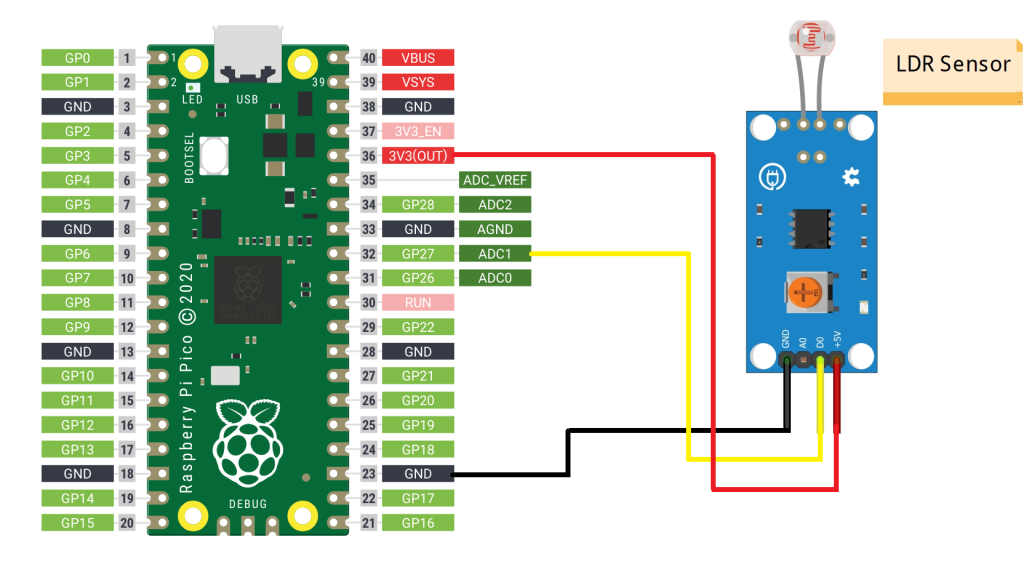
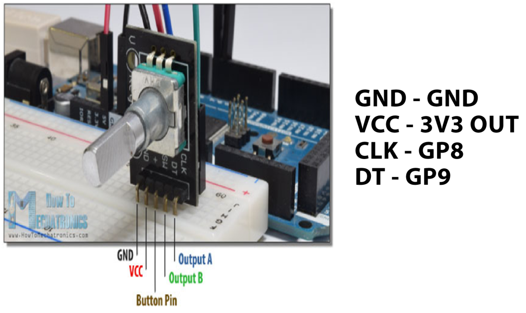
Position encoder sensorல் உள்ள CLK மற்றும் DT பின்களை Raspberry Pi Pico வில் உள்ள GP8 மற்றும் GP9 பின்களுடன் இணைக்க வேண்டும்.
Position encoder ன் +5V மற்றும் ground சப்ளையை Raspberry Pi Pico 3V3 (OUT) மற்றும் gnd உடன் இணைக்க வேண்டும்.
Python program ஐ சரி பார்க்க வேண்டும்.
மின்சுற்றை சரி பார்க்க வேண்டும்.
Python program ஐ ரன் செய்ய வேண்டும்.
Python Program
from machine import Pin
import utime

DT_Pin = Pin(9, Pin.IN, Pin.PULL_UP)
CLK_Pin = Pin(8, Pin.IN, Pin.PULL_UP)
SW = Pin(2, Pin.IN, Pin.PULL_UP)

LEDs = [25,4]

#create an empty list to assing pins in pico
led_pins = []

for x in range(0,2):
    led_pins.append(Pin(LEDs[x], Pin.OUT))

value = 0
previousValue = 1

def rotary_changed():

    global previousValue
    global value

    if previousValue != CLK_Pin.value():
        if CLK_Pin.value() == 0:
            if DT_Pin.value() == 0:

                value = (value - 1)%2
                print("anti-clockwise", value)
            else:

                value = (value + 1)%2
                print("clockwise", value)
        previousValue = CLK_Pin.value()

    if SW.value() == 0:
        print("Button pressed")
        utime.sleep(1)

while True:
    for i in range(0,2):
        led_pins[i].value(0)
        rotary_changed()
        led_pins[value].value(1)
        utime.sleep(0.001)