Creating 2 DC Motors control program using Node MCU
Required Components
- Node MCU -1 no
- L298N Motor Driver -1 no
- 9V Battery -1 no
- 5V DC Motor -2 no
- Motor wheel -2 no
- Cable -1 no
- Jumper Wires -7 no
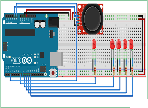
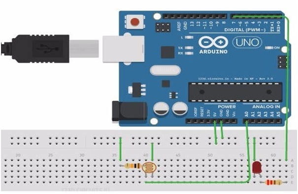
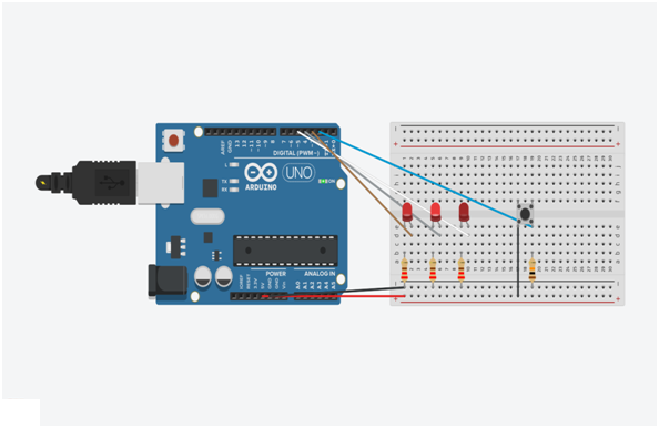
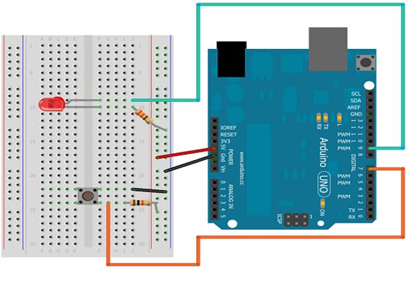
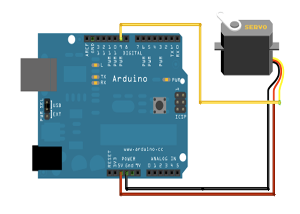
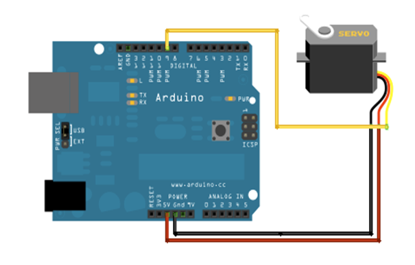
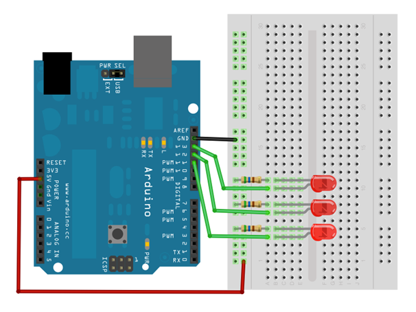
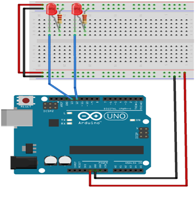
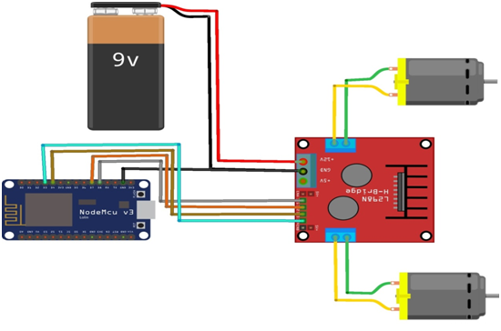
Circuit
Steps
- Make sure the components are working properly.
- Connect the 5V Battery to the L298N Motor Driver.
- Connect the ENA, IN1, IN2, IN3, IN4, ENB pins to the Node MCU pins D2, D0, D1, D7, D6, D5 properly.
- Connect the DC motor pins to the motor driver output pins.
- Connect the Node MCU ground connection to the driver gnd respectively.
- Connect the Power to the NodeMCU.
- Check the Arduino program.
- Check the Circuit Connections.
- Run the Arduino program.
Arduino Program
#include <ESP8266WiFi.h>
const char* ssid = "*****";
const char* password = "*********";
int motor1pin1 = 16; //D0
int motor1pin2 = 5; //D1
int enPin1 = 4; //D2
int motor2pin1 = 13; //D7
int motor2pin2 = 12; //D6
int enPin2 = 14;//D5
WiFiServer server(80);

void setup()
{
  Serial.begin(115200);
  delay(10);
  pinMode(motor1pin1, OUTPUT);
  pinMode(motor1pin2, OUTPUT);
  pinMode(enPin1, OUTPUT);
  digitalWrite(enPin1, HIGH);
  pinMode(motor2pin1, OUTPUT);
  pinMode(motor2pin2, OUTPUT);
  pinMode(enPin2, OUTPUT);
  digitalWrite(enPin2, HIGH);

  Serial.println();
  Serial.println();
  Serial.print("Connecting to ");
  Serial.println(ssid);
  WiFi.begin(ssid, password);

  while (WiFi.status() != WL_CONNECTED)
  {
    delay(500);
    Serial.print(".");
  }
  Serial.println("");
  Serial.println("WiFi connected");
  server.begin();
  Serial.println("Server started");
  Serial.print("Use this URL to connect: ");
  Serial.print("http://");
  Serial.print(WiFi.localIP());
  Serial.println("/");
}

void loop()
{
  WiFiClient client = server.available();
  if (!client)
  {
    return;
  }
  Serial.println("new client");
  while(!client.available())
  {
    delay(1);
  }
  String request = client.readStringUntil('\r');
  Serial.println(request);
  client.flush();
  int value,value1 = LOW,value2 = LOW,value3 = LOW,value4 = LOW;
  if (request.indexOf("/MotorForward") != -1)
  {
    digitalWrite(motor1pin1, HIGH);
    digitalWrite(motor1pin2, LOW);
    digitalWrite(motor2pin1, HIGH);
    digitalWrite(motor2pin2, LOW);
    delay(1000);
    value1 = HIGH;
    value2 = LOW;
    value3 = HIGH;
    value4 = LOW;
  }
  if (request.indexOf("/MotorBackward") != -1)
  {
    digitalWrite(motor1pin1, LOW);
    digitalWrite(motor1pin2, HIGH);
    digitalWrite(motor2pin1, LOW);
    digitalWrite(motor2pin2, HIGH);
    delay(1000);
    value1 = LOW;
    value2 = HIGH;
    value3 = LOW;
    value4 = HIGH;
  }
  if (request.indexOf("/MotorLeft") != -1)
  {
    digitalWrite(motor1pin1, LOW);
    digitalWrite(motor1pin2, HIGH);
    digitalWrite(motor2pin1, HIGH);
    digitalWrite(motor2pin2, LOW);
    delay(1000);
    value1 = LOW;
    value2 = HIGH;
    value3 = HIGH;
    value4 = LOW;
  }
  if (request.indexOf("/MotorRight") != -1)
  {
    digitalWrite(motor1pin1, HIGH);
    digitalWrite(motor1pin2, LOW);
    digitalWrite(motor2pin1, LOW);
    digitalWrite(motor2pin2, HIGH);
    delay(1000);
    value1 = HIGH;
    value2 = LOW;
    value3 = LOW;
    value4 = HIGH;
  }
  if (request.indexOf("/MotorStop") != -1)
  {
    digitalWrite(motor1pin1, LOW);
    digitalWrite(motor1pin2, LOW);
    digitalWrite(motor2pin1, LOW);
    digitalWrite(motor2pin2, LOW);
    delay(1000);
    value1 = LOW;
    value2 = LOW;
    value3 = LOW;
    value4 = LOW;
  }
  client.println("HTTP/1.1 200 OK");
  client.println("Content-Type: text/html");
  client.println(""); //  do not forget this one
  client.println("<!DOCTYPE HTML>");
  client.println("<html>");
  client.print("motor is now: ");

  if(value1 == HIGH && value2 == LOW && value3 == HIGH && value4 == LOW ) {
    client.print("Forward");
  }
  else if(value1 == LOW && value2 == HIGH && value3 == LOW && value4 == HIGH  ) {
    client.print("Backward");
  }
  else if(value1 == LOW && value2 == HIGH && value3 == HIGH && value4 == LOW  ) {
    client.print("Left");
  }
  else if(value1 == HIGH && value2 == LOW && value3 == LOW && value4 == HIGH  ) {
    client.print("Right");
  }
  else if(value1 == LOW && value2 == LOW && value3 == LOW && value4 == LOW  ) {
    client.print("Stop");
  }
  client.println("<br><br>");
  client.println("<a href=\"/MotorForward\"\"><button>Forward </button></a>");
  client.println("<a href=\"/MotorBackward\"\"><button>Backward </button></a><br />");
  client.println("<a href=\"/MotorLeft\"\"><button>Left </button></a>");
  client.println("<a href=\"/MotorRight\"\"><button>Right </button></a><br />");
  client.println("<a href=\"/MotorStop\"\"><button>Stop </button></a>");
  client.println("</html>");
  delay(1);
  Serial.println("Client disonnected");
  Serial.println("");
}
Usage
- Drive
DC motors
- Drive
Stepping motors
- In
Robotics
Projects
- Diwa Robot