Creating LEDs flash program Using Sound sensor
Required Components
- Arduino UNO -1 no
- Sound sensor -1 no
- Resistor 150 ohm -6 no
- LEDs -6 no
- Connecting wires -1 set
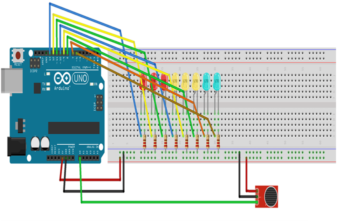
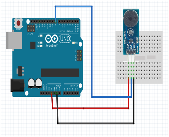
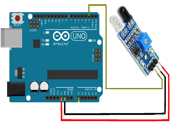
Circuit
Steps
- Make sure the components are working properly.
- Connect the Sound sensor to the Arduino UNO board.
- Connect the Arduino UNO board 8, 9 ,10 ,11 ,12 ,13- pins to the LEDs.
- Connect the Arduino UNO board A0 pin to the Sound sensor.
- Connect the 150 Ohm Resistor to all the LEDs.
- Connect Sound sensor board VCC, GND to 5V, GND of Arduino Uno Board.
- Check the Cicuit Connections.
- Check the Arduino program.
- Run the Arduino program.
Arduino Program
int ledPin1= 8;
int ledPin2= 9;
int ledPin3= 10;
int ledPin4= 11;
int ledPin5= 12;
int ledPin6= 13;
int sensorPin= A0;
int val = 0;

void setup( )
{
  pinMode(ledPin1, OUTPUT);
  pinMode(ledPin2, OUTPUT);
  pinMode(ledPin3, OUTPUT);
  pinMode(ledPin4, OUTPUT);
  pinMode(ledPin5, OUTPUT);
  pinMode(ledPin6, OUTPUT);
  pinMode(sensorPin, INPUT);
  Serial.begin (9600);
}

void loop (  )
{
  val =analogRead(sensorPin);
  Serial.println (val);
  if (val >= 127)
  {
    digitalWrite(ledPin1, HIGH);
  }else {
    digitalWrite(ledPin1, LOW);
  }
  if (val >= 378)
  {
    digitalWrite(ledPin2, HIGH);
  }else {
    digitalWrite(ledPin2, LOW);
  }
  if (val >= 505)
  {
    digitalWrite(ledPin3, HIGH);
  }else {
    digitalWrite(ledPin3, LOW);
  }
  if (val >= 632)
  {
    digitalWrite(ledPin4, HIGH);
  }else
  {
    digitalWrite(ledPin4, LOW);
  }
  if (val >= 759) {
    digitalWrite(ledPin5, HIGH);
  }else
  {
    digitalWrite(ledPin5, LOW);
  }
  if (val >= 886)
  {
    digitalWrite(ledPin6, HIGH);
  }else
  {
    digitalWrite(ledPin6, LOW);
  }
}
Usage
- Security system for Office or Home
- Spy Circuit
- Home Automation
- Smart Phones
- Ambient sound recognition
- Audio amplifier
Projects
- Lightning cloud