Arduino MEGA2560வை பயன்படுத்தி 2 DC மோட்டார்கள் மற்றும் 2 LED-களை ஒரே நேரத்தில் NodeMCU ஐ உபயோகப்படுத்தி கட்டுப்படுத்துவது.
Required Components
- Node MCU -1 no
- L298N Motor Driver -1 no
- 9V Battery -1 no
- 5V DC Motor -2 no
- Motor wheel -2 no
- Cable -1 no
- Jumper Wires -7 no
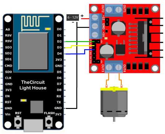
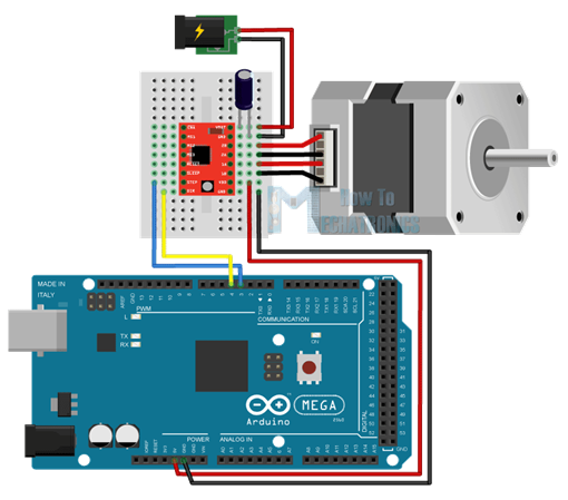
Circuit
Steps
- நாம் பயன்படுத்தும் உபகரணங்கள் சரியாக வேலை செய்கிறதா என்பதை உறுதி செய்து கொள்ளவும்.
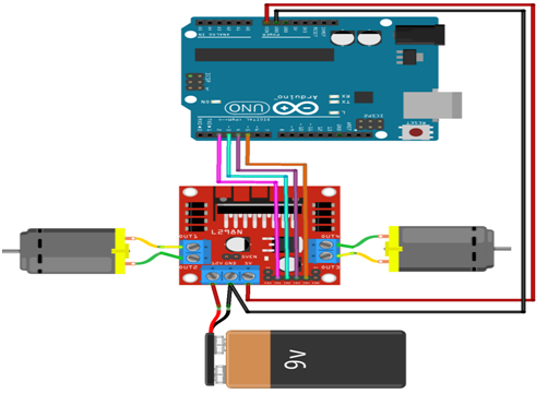
- L298N Motor Driver உடன் 9V Battery ஐ கவனமாக இணைக்க வேண்டும்.
- L298N Motor Driver ENA, IN1, IN2, IN3, IN4, ENB பின்களை Node MCU D2, D0, D1, D7, D6, D5 உடன் இணைக்க வேண்டும்.
- L298N Motor Driver gnd உடன் Node MCU gnd ஐ இணைக்க வேண்டும்.
- L298N Motor Driver OUTPUT பின்களுடன் DC மோட்டார் OUTPUT பின்களை இணைக்க வேண்டும்.
- 2 LED Cathodes(+) & Anode (-) பின்களை Arduino MEGA 2560 Board D3, D4 பின்கள் & gnd உடன் இணைக்க வேண்டும்.
- Node MCU உடன் Power ஐ இணைக்க வேண்டும்.
- Arduino program ஐ சரி பார்க்க வேண்டும்.
- மின்சுற்றை சரி பார்க்க வேண்டும்.
- Arduino program ஐ ரன் செய்ய வேண்டும்.
Arduino Program
#include <ESP8266WiFi.h>
const char* ssid = "*****";
const char* password = "********";
int motor1pin1 = 16; //D0
int motor1pin2 = 5; //D1
int enPin1 = 4; //D2
int motor2pin1 = 13; //D7
int motor2pin2 = 12; //D6
int enPin2 = 14;//D5

int led1 = 0; //D3
int led2 = 2; //D4
WiFiServer server(80);

void setup()
{
  Serial.begin(115200);
  delay(10);
  pinMode(motor1pin1, OUTPUT);
  pinMode(motor1pin2, OUTPUT);
  pinMode(enPin1, OUTPUT);
  digitalWrite(enPin1, HIGH);
  pinMode(motor2pin1, OUTPUT);
  pinMode(motor2pin2, OUTPUT);
  pinMode(enPin2, OUTPUT);
  digitalWrite(enPin2, HIGH);

  pinMode(led1,OUTPUT);
  pinMode(led2,OUTPUT);

  Serial.println();
  Serial.println();
  Serial.print("Connecting to ");
  Serial.println(ssid);
  WiFi.begin(ssid, password);

  while (WiFi.status() != WL_CONNECTED) {
    delay(500);
    Serial.print(".");
  }
  Serial.println("");
  Serial.println("WiFi connected");
  server.begin();
  Serial.println("Server started");
  Serial.print("Use this URL to connect: ");
  Serial.print("http://");
  Serial.print(WiFi.localIP());
  Serial.println("/");
}

void loop()
{
  WiFiClient client = server.available();
  if (!client) {
    return;
  }
  Serial.println("new client");
  while(!client.available()){
    delay(1);
  }
  String request = client.readStringUntil('\r');
  Serial.println(request);
  client.flush();
  int value,value1 = LOW,value2 = LOW,value3 = LOW,value4 = LOW;
  if (request.indexOf("/MotorForward") != -1)
  {
    digitalWrite(motor1pin1, HIGH);
    digitalWrite(motor1pin2, LOW);
    digitalWrite(motor2pin1, HIGH);
    digitalWrite(motor2pin2, LOW);
    delay(1000);
    value1 = HIGH;
    value2 = LOW;
    value3 = HIGH;
    value4 = LOW;
  }
  if (request.indexOf("/MotorBackward") != -1)
  {
    digitalWrite(motor1pin1, LOW);
    digitalWrite(motor1pin2, HIGH);
    digitalWrite(motor2pin1, LOW);
    digitalWrite(motor2pin2, HIGH);
    delay(1000);
    value1 = LOW;
    value2 = HIGH;
    value3 = LOW;
    value4 = HIGH;
  }
  if (request.indexOf("/MotorLeft") != -1)
  {
    digitalWrite(motor1pin1, LOW);
    digitalWrite(motor1pin2, HIGH);
    digitalWrite(motor2pin1, HIGH);
    digitalWrite(motor2pin2, LOW);
    delay(1000);
    value1 = LOW;
    value2 = HIGH;
    value3 = HIGH;
    value4 = LOW;
  }
  if (request.indexOf("/MotorRight") != -1)
  {
    digitalWrite(motor1pin1, HIGH);
    digitalWrite(motor1pin2, LOW);
    digitalWrite(motor2pin1, LOW);
    digitalWrite(motor2pin2, HIGH);
    delay(1000);
    value1 = HIGH;
    value2 = LOW;
    value3 = LOW;
    value4 = HIGH;
  }
  if (request.indexOf("/MotorStop") != -1)
  {
    digitalWrite(motor1pin1, LOW);
    digitalWrite(motor1pin2, LOW);
    digitalWrite(motor2pin1, LOW);
    digitalWrite(motor2pin2, LOW);
    delay(1000);
    value1 = LOW;
    value2 = LOW;
    value3 = LOW;
    value4 = LOW;
  }

  if (request.indexOf("/LedOn") != -1)
  {
    digitalWrite(led1,HIGH);
    digitalWrite(led2,HIGH);
    delay(2000);
    value = HIGH;
  }

  if (request.indexOf("/LedOn") != -1)
  {
    digitalWrite(led1,LOW);
    digitalWrite(led2,LOW);
    delay(2000);
    value = LOW;
  }
  client.println("HTTP/1.1 200 OK");
  client.println("Content-Type: text/html");
  client.println(""); //  do not forget this one
  client.println("<!DOCTYPE HTML>");
  client.println("<html>");
  client.print("motor is now: ");

  if(value1 == HIGH && value2 == LOW && value3 == HIGH && value4 == LOW ) {
    client.print("Forward");
  }
  else if(value1 == LOW && value2 == HIGH && value3 == LOW && value4 == HIGH  ) {
    client.print("Backward");
  }
  else if(value1 == LOW && value2 == HIGH && value3 == HIGH && value4 == LOW  ) {
    client.print("Left");
  }
  else if(value1 == HIGH && value2 == LOW && value3 == LOW && value4 == HIGH  ) {
    client.print("Right");
  }
  else if(value1 == LOW && value2 == LOW && value3 == LOW && value4 == LOW  ) {
    client.print("Stop");
  }
  else if( value = HIGH) {
    client.print("LedOn");
  }
  else if( value = LOW) {
    client.print("LedOff");
  }
  client.println("<br><br>");
  client.println("<a href=\"/MotorForward\"\"><button>Forward </button></a>");
  client.println("<a href=\"/MotorBackward\"\"><button>Backward </button></a><br />");
  client.println("<a href=\"/MotorLeft\"\"><button>Left </button></a>");
  client.println("<a href=\"/MotorRight\"\"><button>Right </button></a><br/>");
  client.println("<a href=\"/MotorStop\"\"><button>Stop </button></a>");
  client.println("<a href=\"/LedOn\"\"><button>LedOn </button></a>");
  client.println("<a href=\"/LedOff\"\"><button>LedOff </button></a>");
  client.println("</html>");
  delay(1);
  Serial.println("Client disonnected");
  Serial.println("");
}
Projects
- DIWA Robot