Arduino Tutorials – Lesson 38 – Use A Buzzer Module Using Raspberry Pi Pico

To control Buzzer using Raspberry Pi Pico

Required Components

  1. Buzzer module _ 1 no
  2. Raspberry Pi Pico _ 1 no
  3. Connecting wires _ 1 set

Circuit

Steps

  1. Make sure the components are working properly.
  2. Connect the Raspberry Pi Pico board GP15th pin to the Buzzer.
  3. Connect Buzzer board GND to GND of Raspberry Pi Pico Board.
  4. Check the Electrical Circuit.
  5. Check the Arduino program.
  6. Run the Arduino program.

Arduino Program

const int buzzer = 15;

void setup( )
{
  pinMode(buzzer, OUTPUT);
}

void loop()
{
  tone(buzzer, 1000);
  delay(1000);
  noTone(buzzer);
  delay(1000);        
}

Arduino Tutorials – Lesson 37 – Double led blink using Raspberry Pi Pico

To check double LED blink using Raspberry Pi Pico

Required Components

  1. Led _ 2 no
  2. Raspberry Pi Pico board _ 1 no
  3. Connecting wires _ 1 set

Circuit

Steps

  1. Make sure the components are working properly.
  2. Connect Led GND pins to Raspberry Pi Pico GND pins respectively.
  3. Connect Raspberry Pi Pico GP2, GP20 pins to the each LED anode pins.
  4. Check the Arduino program.
  5. Check the circuit connections.
  6. Run the Arduino program.

Arduino Program

int Led1 = 2;
int Led2 = 20;

void setup() 
{
  pinMode(Led1, OUTPUT);
  pinMode(Led2, OUTPUT);

}

void loop() 
{
  digitalWrite(Led1, HIGH);
  digitalWrite(Led2, HIGH);
  delay(1000);

  digitalWrite(Led1, LOW);
  digitalWrite(Led2, LOW);
  delay(1000);
}

Arduino Tutorials – Lesson 36 – Single LED Blink Using Raspberry Pi Pico

To check single LED blink using Raspberry Pi Pico.

Required Components

  1. Led _1 no
  2. Resister 330Ω _1 no
  3. Raspberry Pi Pico board _1 no
  4. Connecting wires _1 set

Circuit

Steps

  1. Make sure the components are working properly.
  2. Connect 330 Ω Resistor to the LED Anode (+) pin and LED cathode (-) pin to Gnd.
  3. Connect Raspberry Pi Pico pin 28 to the LED anode pin.
  4. Check the Arduino program.
  5. Check the circuit connections.
  6. Run the Arduino program.

Arduino Program

int led1 = 28;

void setup ( )
{
  pinMode (led1, OUTPUT);
}

void loop ( )
{
  digitalWrite (led1, HIGH);
  delay (3000);
  digitalWrite (led1, LOW);
  delay (1000);
} 

Arduino Tutorials – Lesson 35 – Vibration Sensor on Arduino UNO

Creating Vibration Sensor program using Arduino UNO

Required Components

  1. Arduino Uno Board _1 no
  2. Vibration Sensor _1 no
  3. USB Cable _1 no
  4. Connecting Wires _1 set

Circuit

Steps

  1. Make sure the components are working properly.
  2. Connect the Arduino UNO 7th pin to the Vibration Sensor DO pin.
  3. Connect the Arduino UNO 5V, GND to the Vibration Sensor VCC, GND.
  4. The LED 13th pin is Default.
  5. Connect the ground connection respectively.
  6. Check the Arduino program.
  7. Check the circuit connections.
  8. Run the Arduino program.

Arduino Program

int vib_pin=7;
int led_pin=13;

void setup() 
{
  pinMode(vib_pin,INPUT);
  pinMode(led_pin,OUTPUT);
  Serial.begin(9600);
}

void loop() 
{
  int val;
  long measurement =vibration();
  delay(50);
  Serial.println(measurement);
  if (measurement > 50){
    digitalWrite(led_pin, HIGH);
  }
  else{
    digitalWrite(led_pin, LOW); 
  }
}
 
long vibration()
{
  long measurement=pulseIn (vib_pin, HIGH);  
  return measurement;
}

Usage

  1. Food & Beverage
  2. Water & Waste water
  3. Oil & Gas
  4. Automotive

Arduino Tutorials – Lesson 34 – OLED Display Using Arduino UNO

To give the input (Numbers) to Serial Monitor and get the output in OLED Display.

Required Components

  1. OLED Display -1 no
  2. Arduino UNO Board -1 no
  3. USB Cable -1 no
  4. Connecting wires -1 set

Circuit

Steps

  1. Make sure the components are working properly.
  2. Connect OLED Display gnd & VCC to the Arduino UNO Board gnd & 5V.
  3. Connect Arduino pin A4 & A5 to the OLED Display SDA & SCL.
  4. Check the Arduino program.
  5. Check the circuit connections.
  6. Run the Arduino program.

Arduino Program

#include <SPI.h>
#include <Wire.h>
#include <Adafruit_GFX.h>
#include <Adafruit_SSD1306.h>

Adafruit_SSD1306 display(-1);

void setup()   
{                
  Serial.begin(9600);
  display.begin(SSD1306_SWITCHCAPVCC, 0x3C);  
}

void loop() 
{
  if (Serial.available() > 0) 
  {   
    String a = Serial.readString();      
    display.clearDisplay();
    display.setTextSize(2);
    display.setTextColor(WHITE);
    display.setCursor(10,10);
    display.println(a);
    display.display();
    delay(2000);
    Serial.print("Number received: ");
    Serial.println(a);   
  } 
}

Usage

  1. TVs
  2. Cellphone screens
  3. Computer screens
  4. Keyboards
  5. Lights
  6. Portable device displays

Arduino Tutorials – பாடம் 34 – OLED Display Using Arduino UNO

Serial Monitor-ல்  Input (எண்கள்) கொடுத்து , Output ஐ OLED டிஸ்ப்ளேயில் பெறுதல்.

Required Components

  1. OLED Display -1 no
  2. Arduino UNO Board -1 no
  3. USB Cable -1 no
  4. Connecting wires -1 set

Circuit

Steps

  1. நாம் பயன்படுத்தும் உபகரணங்கள் சரியாக வேலை செய்கிறதா என்பதை உறுதி செய்து கொள்ளவும்.
  2. OLED Display gnd & VCC ஐ Arduino UNO Board gnd & 5V உடன் இணைக்க வேண்டும்.
  3. Arduino UNO Board இன் A4 & A5 ஐ OLED Display SDA & SCL உடன் இணைக்க வேண்டும்.
  4. Arduino program ஐ சரி பார்க்க வேண்டும்.
  5. மின்சுற்றை சரி பார்க்க வேண்டும்.
  6. Arduino program ஐ ரன் செய்ய வேண்டும்.

Arduino Program

#include <SPI.h>
#include <Wire.h>
#include <Adafruit_GFX.h>
#include <Adafruit_SSD1306.h>

Adafruit_SSD1306 display(-1);

void setup()   
{                
  Serial.begin(9600);
  display.begin(SSD1306_SWITCHCAPVCC, 0x3C);  
}

void loop() 
{
  if (Serial.available() > 0) 
  {   
    String a = Serial.readString();      
    display.clearDisplay();
    display.setTextSize(2);
    display.setTextColor(WHITE);
    display.setCursor(10,10);
    display.println(a);
    display.display();
    delay(2000);
    Serial.print("Number received: ");
    Serial.println(a);   
  } 
}

Usage

  1. டி.வி. (TVs)
  2. செல்போன் திரைகள் (Cellphone screens)
  3. கணினித் திரைகள் (Computer screens)
  4. விசைப்பலகைகள் (Keyboards)
  5. விளக்குகள் (Lights)
  6. சிறிய சாதன காட்சிகள் (Portable device displays)

Arduino Tutorials – பாடம் 33 – DF Player mini using Arduino MEGA2560

DF Player mini ஐ Arduino Uno Board ஐ பயன்படுத்தி சோதனை செய்வது.

Required Components

  1. DF Player mini -1 no
  2. Data Cable -1 no
  3. Connecting Wires -1 set
  4. Arduino Uno -1 no
  5. Speaker -1 no
  6. Resistor 1000ohm -1 no

Circuit

Steps

  1. நாம் பயன்படுத்தும் உபகரணங்கள் சரியாக வேலை செய்கிறதா என்பதை உறுதி செய்து கொள்ளவும்.
  2. Arduino Uno Boardன் +5V மற்றும் ground சப்ளையை DF Player Mini VCC மற்றும் GND உடன் இணைக்க வேண்டும்.
  3. Resistor ன் ஒரு முனையை DF Player Mini RX மற்றும் Resistor ன் மறு முனையை Arduino Uno Board 1 அல்லது TX உடன் இணைக்க வேண்டும்.
  4. Resistor ன் ஒரு முனையை DF Player Mini RX மற்றும் Resistor ன் மறு முனையை Arduino Uno Board 1 அல்லது TX உடன் இணைக்க வேண்டும்.
  5. மற்றொரு Resistor ன் ஒரு முனையை DF Player Mini TX மற்றும் Resistor ன் மறு முனையை Arduino Uno Board 0 அல்லது RX உடன் இணைக்க வேண்டும்.
  6. DF Player Mini SPK-1 & SPK-2 ஐ Speker உடன் இணைக்க வேண்டும்.
  7. Arduino program ஐ சரி பார்க்க வேண்டும்.
  8. மின்சுற்றை சரி பார்க்க வேண்டும்.
  9. Arduino program ஐ ரன் செய்ய வேண்டும்.

Arduino Program

#include "SoftwareSerial.h"
#include <DFMiniMp3.h> 
#define DEBUG 0
class Mp3Notify
{
public:
 static void OnError(uint16_t errorCode)
 {
  Serial.println();
  Serial.print("Com Error ");
  Serial.println(errorCode);
 }
 static void OnPlayFinished(uint16_t track)
 {
  Serial.print("Play finished for #");
  Serial.println(track);
 }
 static void OnCardOnline(uint16_t code)
 {
  Serial.println("Card online ");
 }
 static void OnCardInserted(uint16_t code)
 {
  Serial.println("Card inserted ");
 }
 static void OnCardRemoved(uint16_t code)
 {
  Serial.println("Card removed ");
 }
};
SoftwareSerial secondarySerial(10, 11); 
DFMiniMp3<SoftwareSerial, Mp3Notify> mp3(secondarySerial);
const int LDRpin = A0; 
const int LEDpin = 13; 
int Song=1; 
int ldrStatus;
boolean onStatus = true;
boolean takeLowTime;
long unsigned int timeoutTimer = 0, resetCount = 0;
long unsigned int pause = 2000;

void setup()
{
 Serial.begin(115200);
 if (DEBUG) Serial.println("initializing...");
 pinMode(LDRpin, INPUT); 
 pinMode(LEDpin, OUTPUT);
 mp3.begin();
 mp3.reset();
 uint16_t volume = mp3.getVolume();
 Serial.print("volume ");
 Serial.println(volume);
 mp3.setVolume(20);
 uint16_t count = mp3.getTotalTrackCount();
 Serial.print("files ");
 Serial.println(count);
 uint16_t mode = mp3.getPlaybackMode();
 Serial.print("playback mode ");
 Serial.println(mode);
 if (DEBUG) Serial.println("starting...");
 mp3.playFolderTrack(6, Song);
}

void loop()
{
 ldrStatus = analogRead(LDRpin);
 if (ldrStatus >=300)
  {
    digitalWrite(LEDpin, HIGH);
    mp3.start();
    onStatus = true;
  }
 else 
  {
    digitalWrite(LEDpin, LOW);
    mp3.pause();
  }

 mp3.loop(); 
}

Usage

  1. தீ எச்சரிக்கை குரல் எழுப்புதல் (Fire alarm voice prompts).
  2. கார் வழிசெலுத்தல் குரல் ஒளிபரப்பு (Car navigation voice broadcast).
  3. ரயில் நிலையம், பஸ் பாதுகாப்பு ஆய்வு குரல் எழுப்புதல் (Railway station, bus safety inspection voice prompts).
  4. மின்சாரம், தகவல் தொடர்பு, நிதி வணிக மண்டபக் குரல் எழுப்புதல் (Electricity, communications, financial business hall voice prompts).

Arduino Tutorials – பாடம் 32 – L298N Motor Driver with Node MCU

2 DC மோட்டார்களை  NodeMCU ஐ உபயோகப்படுத்தி கட்டுப்படுத்துவது.

Required Components

  1. Node MCU -1 no
  2. L298N Motor Driver -1 no
  3. 9V Battery -1 no
  4. 5V DC Motor -2 no
  5. Motor wheel -2 no
  6. Cable -1 no
  7. Jumper Wires -7 no

Circuit

Steps

  1. நாம் பயன்படுத்தும் உபகரணங்கள் சரியாக வேலை செய்கிறதா என்பதை உறுதி செய்து கொள்ளவும்.
  2. L298N Motor Driver உடன் 5V Battery ஐ கவனமாக இணைக்க வேண்டும்.
  3. L298N Motor Driver ENA, IN1, IN2, IN3, IN4, ENB பின்களை Node MCU D2, D0, D1, D7, D6, D5 உடன் இணைக்க வேண்டும்.
  4. L298N Motor Driver gnd உடன் Node MCU gnd ஐ இணைக்க வேண்டும்.
  5. L298N Motor Driver OUTPUT பின்களுடன் DC மோட்டார் OUTPUT பின்களை இணைக்க வேண்டும்.
  6. Node MCU உடன் Power ஐ இணைக்க வேண்டும்.
  7. Arduino program ஐ சரி பார்க்க வேண்டும்.
  8. மின்சுற்றை சரி பார்க்க வேண்டும்.
  9. Arduino program ஐ ரன் செய்ய வேண்டும்.

Arduino Program

#include <ESP8266WiFi.h>
const char* ssid = "*****";
const char* password = "*********";
int motor1pin1 = 16; //D0
int motor1pin2 = 5; //D1
int enPin1 = 4; //D2
int motor2pin1 = 13; //D7
int motor2pin2 = 12; //D6
int enPin2 = 14;//D5
WiFiServer server(80);

void setup() 
{
  Serial.begin(115200);
  delay(10);
  pinMode(motor1pin1, OUTPUT);
  pinMode(motor1pin2, OUTPUT);
  pinMode(enPin1, OUTPUT);
  digitalWrite(enPin1, HIGH);
  pinMode(motor2pin1, OUTPUT);
  pinMode(motor2pin2, OUTPUT);
  pinMode(enPin2, OUTPUT);
  digitalWrite(enPin2, HIGH);
  
  Serial.println();
  Serial.println();
  Serial.print("Connecting to ");
  Serial.println(ssid);
  WiFi.begin(ssid, password);

  while (WiFi.status() != WL_CONNECTED) 
  {
    delay(500);
    Serial.print(".");
  }
  Serial.println("");
  Serial.println("WiFi connected");
  server.begin();
  Serial.println("Server started");
  Serial.print("Use this URL to connect: ");
  Serial.print("http://");
  Serial.print(WiFi.localIP());
  Serial.println("/");
}

void loop() 
{
  WiFiClient client = server.available();
  if (!client) 
  {
    return;
  }
  Serial.println("new client");
  while(!client.available())
  {
    delay(1);
  }
  String request = client.readStringUntil('\r');
  Serial.println(request);
  client.flush();
  int value,value1 = LOW,value2 = LOW,value3 = LOW,value4 = LOW;
  if (request.indexOf("/MotorForward") != -1)
  {
    digitalWrite(motor1pin1, HIGH);
    digitalWrite(motor1pin2, LOW);
    digitalWrite(motor2pin1, HIGH);
    digitalWrite(motor2pin2, LOW);
    delay(1000);
    value1 = HIGH;
    value2 = LOW;
    value3 = HIGH;
    value4 = LOW;
  }
  if (request.indexOf("/MotorBackward") != -1)
  {
    digitalWrite(motor1pin1, LOW);
    digitalWrite(motor1pin2, HIGH);
    digitalWrite(motor2pin1, LOW);
    digitalWrite(motor2pin2, HIGH);
    delay(1000);
    value1 = LOW;
    value2 = HIGH;
    value3 = LOW;
    value4 = HIGH;
  }
  if (request.indexOf("/MotorLeft") != -1)
  {
    digitalWrite(motor1pin1, LOW);
    digitalWrite(motor1pin2, HIGH);
    digitalWrite(motor2pin1, HIGH);
    digitalWrite(motor2pin2, LOW);
    delay(1000);
    value1 = LOW;
    value2 = HIGH;
    value3 = HIGH;
    value4 = LOW;
  }
  if (request.indexOf("/MotorRight") != -1)
  {
    digitalWrite(motor1pin1, HIGH);
    digitalWrite(motor1pin2, LOW);
    digitalWrite(motor2pin1, LOW);
    digitalWrite(motor2pin2, HIGH);
    delay(1000);
    value1 = HIGH;
    value2 = LOW;
    value3 = LOW;
    value4 = HIGH;
  }
  if (request.indexOf("/MotorStop") != -1)
  {
    digitalWrite(motor1pin1, LOW);
    digitalWrite(motor1pin2, LOW);
    digitalWrite(motor2pin1, LOW);
    digitalWrite(motor2pin2, LOW);
    delay(1000);
    value1 = LOW;
    value2 = LOW;
    value3 = LOW;
    value4 = LOW;
  }
  client.println("HTTP/1.1 200 OK");
  client.println("Content-Type: text/html");
  client.println(""); //  do not forget this one
  client.println("<!DOCTYPE HTML>");
  client.println("<html>");
  client.print("motor is now: ");
  
  if(value1 == HIGH && value2 == LOW && value3 == HIGH && value4 == LOW ) {
    client.print("Forward");
  }
  else if(value1 == LOW && value2 == HIGH && value3 == LOW && value4 == HIGH  ) {
    client.print("Backward");
  }
  else if(value1 == LOW && value2 == HIGH && value3 == HIGH && value4 == LOW  ) {
    client.print("Left");
  }
  else if(value1 == HIGH && value2 == LOW && value3 == LOW && value4 == HIGH  ) {
    client.print("Right");
  }
  else if(value1 == LOW && value2 == LOW && value3 == LOW && value4 == LOW  ) {
    client.print("Stop");
  }
  client.println("<br><br>");
  client.println("<a href=\"/MotorForward\"\"><button>Forward </button></a>");
  client.println("<a href=\"/MotorBackward\"\"><button>Backward </button></a><br />");
  client.println("<a href=\"/MotorLeft\"\"><button>Left </button></a>");
  client.println("<a href=\"/MotorRight\"\"><button>Right </button></a><br />");
  client.println("<a href=\"/MotorStop\"\"><button>Stop </button></a>");
  client.println("</html>");
  delay(1);
  Serial.println("Client disonnected");
  Serial.println("");
}

Usage

  1. நேரோட்ட மின்சார இயக்கி(Drive DC motors)
  2. படிநிலை இயக்கி(Drive Stepping motors)
  3. ரோபாட்டிக்ஸ்(In Robotics)

Projects

  1. திவா ரோபோட் (Diwa Robot)

Arduino Tutorials – பாடம் 31 – Micro Metal Gear Motor with Encoder

Arduino MEGA2560வை பயன்படுத்தி 2 Encoder மோட்டார்களை துல்லியமாக கட்டுப்படுத்துவது.

Required Components

  1. Arduino MEGA2560 -1 no
  2. Motor control shield(L293D) -1 no
  3. Micro Metal Gear Motor with Encoder -2 no
  4. Motor Wheel -2 no
  5. Bread Board -1 no
  6. Jumper Wires(Male to Male) -11 no
  7. Voltage Converter(5V-3.3V) -1 no
  8. 5V Battery -1 no
  9. USB cable -1 no

Steps

  1. நாம் பயன்படுத்தும் உபகரணங்கள் சரியாக வேலை செய்கிறதா என்பதை உறுதி செய்து கொள்ளவும்.
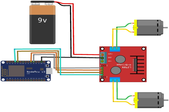
  2. Motor control shield(L293D) உடன் +5V battery இணைக்க வேண்டும்.
  3. +5V பேட்டரி இணைப்புகளை சரியாகவும் கவனமாகவும் இணைக்க வேண்டும்.
  4. Motor control shield(L293D) M4ஐ முதலாவது மோட்டார் M1, M2 உடனும், Motor control shield(L293D) M3ஐ இரண்டாவது மோட்டார் M1, M2 உடனும் இணைக்க வேண்டும்.
  5. Arduino 5V, gnd ஐ voltage converter V IN,gnd உடன் கவனமாக இணைக்க வேண்டும்.
  6. voltage converter V OUT,gnd ஐ முதலாவது மோட்டார் VCC, gnd உடனும், இரண்டாவது மோட்டார் VCC, gnd உடனும் கவனமாக இணைக்க வேண்டும்.
  7. முதலாவது மோட்டார் C1,C2 பின்களை Arduino MEGA2560 18,19 பின்களுடனும், இரண்டாவது மோட்டார் C1,C2 பின்களை Arduino MEGA2560 20,21 பின்களுடனும் இணைக்க வேண்டும்.
  8. Arduino program ஐ சரி பார்க்க வேண்டும்.
  9. மின்சுற்றை சரி பார்க்க வேண்டும்.
  10. Arduino program ஐ ரன் செய்ய வேண்டும்.

Arduino Program

#include <AFMotor.h>
#include <Encoder.h>
AF_DCMotor motor1(4);
AF_DCMotor motor2(3);
Encoder myEnc1(21,20);
Encoder myEnc2(18,19);
long oldPosition1  = -999;
long oldPosition2  = -999;
long m1Pos = 0;
long m1Dir = 0;
long m2Pos = 0;
long m2Dir = 0;
long md1=2000;
long md2=2000;

void setup()
{
  Serial.begin(9600);
  Serial.println("Motor test!");
  
  motor1.setSpeed(200);
  motor2.setSpeed(200);
  motor1.run(RELEASE);
  motor2.run(RELEASE);
  motor1Move(md1,0);
  motor2Move(md2,0);
}

void loop()
{
  checkMotor1();
  checkMotor2();
  delay(5);
}

void motor1Move(int d1,int d2)
{
  m1Pos=d1;
  m1Dir = d2;
  if (d2==0)
  {
    motor1.run(FORWARD);
  }
  else if (d2==1)
  {
    motor1.run(BACKWARD);
  }
}

void motor2Move(int d1,int d2)
{
  m2Pos=d1;
  m2Dir = d2;
  if (d2==0)
  {
    motor2.run(FORWARD);
  }
  else if (d2==1)
  {
    motor2.run(BACKWARD);
  }
}

void checkMotor1()
{
  long newPosition1 = myEnc1.read();
  if (m1Dir==0)
  {
    if ( newPosition1>m1Pos)
    {
      m1Pos=0;
      motor1.run(RELEASE);
      myEnc1.write(0);
      motor1Move(md1,1);
    }
  }
  else
  {
    if ( abs(newPosition1)>m1Pos)
    {
      m1Pos=0;
      motor1.run(RELEASE);
      myEnc1.write(0);
      
      motor1Move(md1,0);
    }
  }
}

void checkMotor2()
{
  long newPosition2 = myEnc2.read();
  if (m2Dir==0)
  {
    if ( newPosition2>m2Pos)
    {
      m2Pos=0;
      motor2.run(RELEASE);
      myEnc2.write(0);
      motor2Move(md2,1);
    }
  }
  else
  {
    if ( abs(newPosition2)>m2Pos)
    {
      m2Pos=0;
      motor2.run(RELEASE);
      myEnc2.write(0);
      motor2Move(md2,0);
    }
  }
}

Arduino Tutorials – பாடம் 30 – Sharp Distance IR Sensor Module (2Y0A02 F 5x) using ARDUINO UNO

ஒரு குறிப்பிட்ட பொருளின் தொலைவைக் கண்டறிவது அதன் அளவெல்லை (20-150) cm.

Required Components

  1. Arduino Uno Board -1 no
  2. Sharp IR 2Y0A02 F 5x sensor -1 no
  3. Data Cable -1 no
  4. Jumper wires -3 no

Circuit

Steps

  1. நாம் பயன்படுத்தும் உபகரணங்கள் சரியாக வேலை செய்கிறதா என்பதை உறுதி செய்து கொள்ளவும்.
  2. Sharp IR sensorல் உள்ள SDA மற்றும் SCL பின்களை Arduino வில் உள்ள SDA மற்றும் SCL பின்களுடன் இணைக்க வேண்டும்.
  3. Arduino Uno Boardன் +5V மற்றும் ground சப்ளையை Sharp IR sensor உடன் இணைக்க வேண்டும்.
  4. Sharp IR sensor டேட்டா பின்னை Arduino Uno Board A0 pin உடன் இணைக்க வேண்டும்.
  5. Arduino program ஐ சரி பார்க்க வேண்டும்.
  6. மின்சுற்றை சரி பார்க்க வேண்டும்.
  7. Arduino program ஐ ரன் செய்ய வேண்டும்.

Arduino Program

#include <SharpIR.h>
#define ir A0
#define model 20150
SharpIR SharpIR(ir, model);

void setup() 
{
  Serial.begin(9600);
}

void loop() 
{
  delay(2000);   
  unsigned long pepe1=millis();
  int dis=SharpIR.distance();  
  Serial.print("Mean distance: ");  
  Serial.println(dis);
  
  unsigned long pepe2=millis()-pepe1;  
  Serial.print("Time taken (ms): ");
  Serial.println(pepe2);
}  

Usage

  1. Touch-less switch (Sanitary equipment, Control of illumination, etc.).
  2. ஆற்றல் சேமிப்பிற்கான Sensor (Sensor for energy saving e.g. ATM, Copier, Laptop computer, LCD monitor).
  3. பொழுதுபோக்கு கருவி (Amusement equipment e.g. Arcade game machine).