Python Tutorials – பாடம் 5 – Sweep Servo Motor Control Using Raspberry Pi Pico

Raspberry Pi Pico வை பயன்படுத்தி Servo மோட்டாரை சுற்ற வைப்பது

Required Components

  1. Servo motor(5V)-1 no
  2. Raspberry Pi Pico board-1 no
  3. Connecting wires-1 set

Circuit

Steps

  1. நாம் பயன்படுத்தும் உபகரணங்கள் சரியாக வேலை செய்கிறதா என்பதை உறுதி செய்து கொள்ளவும்.
  2. Servo மோட்டாருக்கு மூன்று இணைப்புகள் உள்ளன, அதில் ஒன்று data pin, +5v மற்றும் ground.
  3. Raspberry Pi Pico GP15 ஆவது இணைப்பை நேரடியாக மோட்டார் உடன் இணைக்க வேண்டும்.
  4. Servo வில் உள்ள +5v மற்றும் ground ஐ Raspberry Pi Pico VBus மற்றும் gnd உடன் இணைக்க வேண்டும்.
  5. Python program ஐ சரி பார்க்க வேண்டும்.
  6. மின்சுற்றை சரி பார்க்க வேண்டும்.
  7. Python program ஐ ரன் செய்ய வேண்டும்.

Python Program

from machine import Pin,PWM
import utime

MID = 1500000
MIN = 1000000
MAX = 2000000

led = Pin(25,Pin.OUT)
pwm = PWM(Pin(15))

pwm.freq(50)
pwm.duty_ns(MID)

while True:
    pwm.duty_ns(MIN)
    utime.sleep(1)
    pwm.duty_ns(MID)
    utime.sleep(1)
    pwm.duty_ns(MAX)
    utime.sleep(1)

Python Tutorials – பாடம் 4 – Single LED Control With Single Pushbutton

ஒரு புஷ் பட்டன் ஐ பயன்படுத்தி ஒரு LEDஐ ஒளிர வைப்பது

Required Components

  1. LED-1 no
  2. 220 Ω Resistor-1 no
  3. 10 K Ω Resistor-1 no
  4. Pushbutton-1 no
  5. Bread Board-1 no
  6. Raspberry Pi Pico-1 no
  7. Connecting wires-1 Set
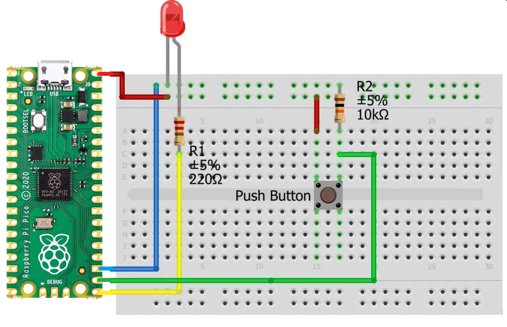
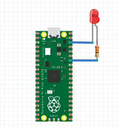
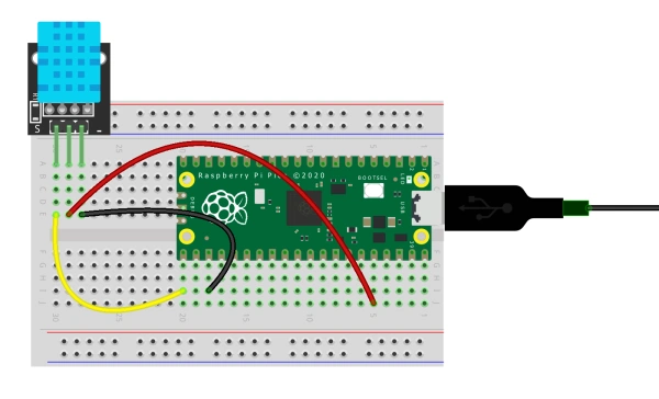
Circuit

Steps

  1. நாம் பயன்படுத்தும் உபகரணங்கள் சரியாக வேலை செய்கிறதா என்பதை உறுதி செய்து கொள்ளவும்.
  2. இரண்டு வகையான மின்தடைகளை எடுத்து கொள்ளவும் ஒன்று 10K மற்றறொன்று 220 Ohm.
  3. 220Ohm மின்தடையை LED உடனும் 10K மின்தடையை சுவிட்ச் உடனும் இணைக்க வேண்டும்.
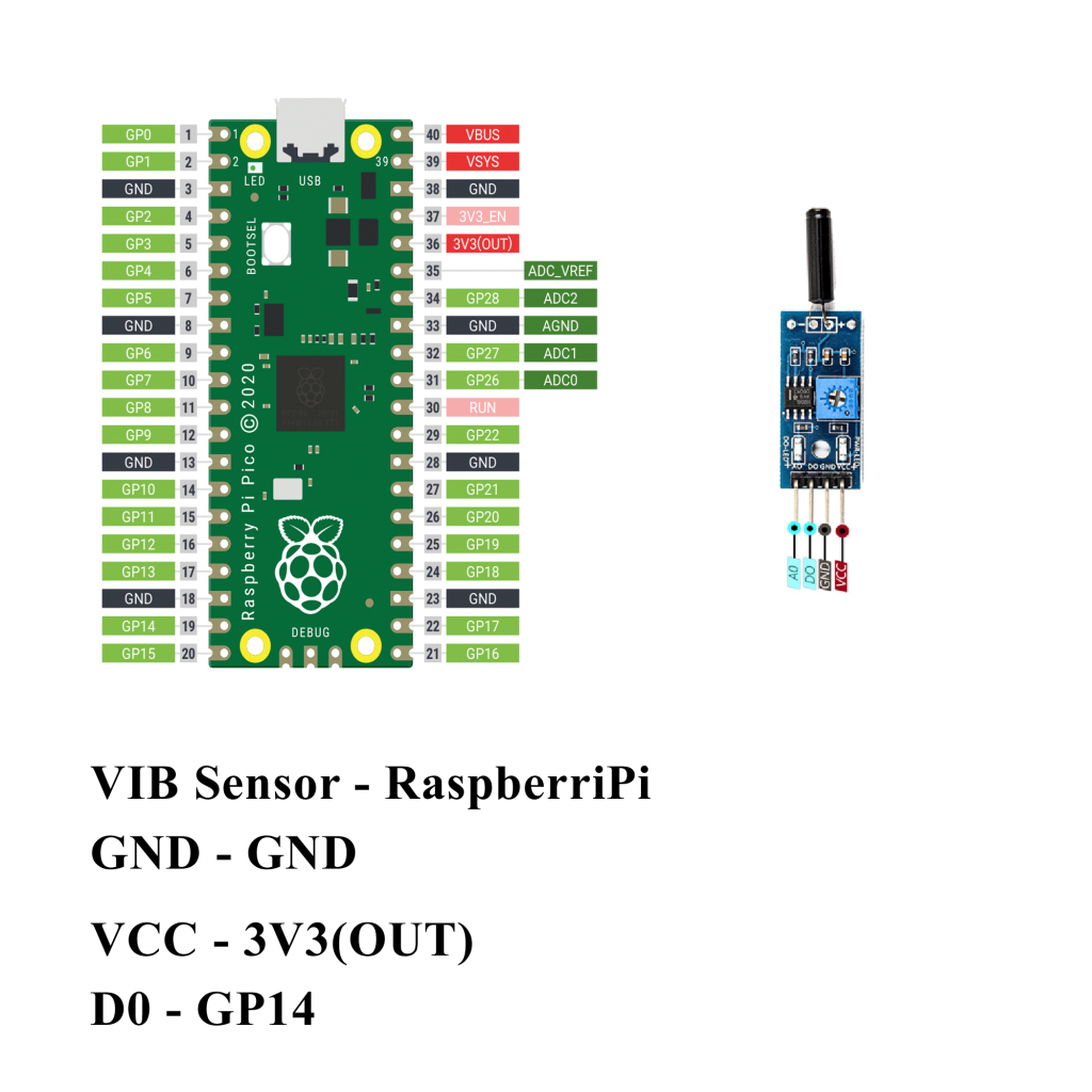
  4. அந்த புஷ்பட்டன் ஐ Raspberry Pi Pico GP17 உடன் இணைக்க வேண்டும்.
  5. 220Ohm மின்தடையை LED + உடன் மற்றும் LED – ஐ GND உடன் இணைக்க வேண்டும்.
  6. 220Ohm மின்தடையை Raspberry Pi Pico GP16 உடன் இணைக்க வேண்டும்.
  7. புஷ் பட்டன் ஐ அழுத்தும் போது LED ஒளிர வேண்டும்.
  8. Python program ஐ சரி பார்க்க வேண்டும்.
  9. மின்சுற்றை சரி பார்க்க வேண்டும்.
  10. Python program ஐ ரன் செய்ய வேண்டும்.

Python Program

from machine import Pin
from time import sleep
led_pin = Pin(16, Pin.OUT)    # 16 number in is Output
push_button = Pin(17, Pin.IN)  # 17 number pin is input

while True:
  
  logic_state = push_button.value()
  if logic_state == True:     # if push_button pressed
      led_pin.value(1)             # led will turn ON
  else:                       # if push_button not pressed
      led_pin.value(0)   

Python Tutorials – பாடம் 3 – Use A Buzzer Module Using Raspberry Pi Pico

Raspberry Pi Pico வை பயன்படுத்தி Buzzer (ஒலிப்பான்) ஐ கட்டுபடுத்துவது

Required Components

  1. Buzzer module-1 no
  2. Raspberry Pi Pico-1 no
  3. Connecting wires-1 set

Circuit

Steps

  1. நாம் பயன்படுத்தும் உபகரணங்கள் சரியாக வேலை செய்கிறதா என்பதை உறுதி செய்து கொள்ளவும்.
  2. Buzzer (ஒலிப்பான்) ஐ Raspberry Pi Pico GP15உடன் இணைக்க வேண்டும்.
  3. Buzzer (ஒலிப்பான்) Ground உடன் Raspberry Pi Pico Ground ஐ இணைக்க வேண்டும்.
  4. Python program ஐ சரி பார்க்க வேண்டும்.
  5. மின்சுற்றை சரி பார்க்க வேண்டும்.
  6. Python program ஐ ரன் செய்ய வேண்டும்.

Python Program

from machine import Pin, PWM
from utime import sleep
buzzer = PWM(Pin(15))

tones = {
"B0": 31,
"C1": 33,
"CS1": 35,
"D1": 37,
"DS1": 39,
"E1": 41,
"F1": 44,
"FS1": 46,
"G1": 49,
"GS1": 52,
"A1": 55,
"AS1": 58,
"B1": 62,
"C2": 65,
"CS2": 69,
"D2": 73,
"DS2": 78,
"E2": 82,
"F2": 87,
"FS2": 93,
"G2": 98,
"GS2": 104,
"A2": 110,
"AS2": 117,
"B2": 123,
"C3": 131,
"CS3": 139,
"D3": 147,
"DS3": 156,
"E3": 165,
"F3": 175,
"FS3": 185,
"G3": 196,
"GS3": 208,
"A3": 220,
"AS3": 233,
"B3": 247,
"C4": 262,
"CS4": 277,
"D4": 294,
"DS4": 311,
"E4": 330,
"F4": 349,
"FS4": 370,
"G4": 392,
"GS4": 415,
"A4": 440,
"AS4": 466,
"B4": 494,
"C5": 523,
"CS5": 554,
"D5": 587,
"DS5": 622,
"E5": 659,
"F5": 698,
"FS5": 740,
"G5": 784,
"GS5": 831,
"A5": 880,
"AS5": 932,
"B5": 988,
"C6": 1047,
"CS6": 1109,
"D6": 1175,
"DS6": 1245,
"E6": 1319,
"F6": 1397,
"FS6": 1480,
"G6": 1568,
"GS6": 1661,
"A6": 1760,
"AS6": 1865,
"B6": 1976,
"C7": 2093,
"CS7": 2217,
"D7": 2349,
"DS7": 2489,
"E7": 2637,
"F7": 2794,
"FS7": 2960,
"G7": 3136,
"GS7": 3322,
"A7": 3520,
"AS7": 3729,
"B7": 3951,
"C8": 4186,
"CS8": 4435,
"D8": 4699,
"DS8": 4978
}

song = ["E5","G5","A5","P","E5","G5","B5","A5","P","E5","G5","A5","P","G5","E5"]
#song = ["G4","A4","C5","F5","D5","F5","G5","F5","D5","C5","A4","C5","D5","F5","G5","G5","G5","A5","G5","G5","F5"]
#song = ["B4","B4","B4","C5","C5","C5","F5","F5","G5","F5","D5","C5","C5","B4"]


def playtone(frequency):
    buzzer.duty_u16(5000)
    buzzer.freq(frequency)

def bequiet():
    buzzer.duty_u16(0)

def playsong(mysong):
    for i in range(len(mysong)):
        if (mysong[i] == "P"):
            bequiet()
        else:
            playtone(tones[mysong[i]])
        sleep(0.3)
    bequiet()
playsong(song)

Python Tutorials – பாடம் 2 – Double led blink using Raspberry Pi Pico

Raspberry Pi Pico வை பயன்படுத்தி இரண்டு LED ஐ ஒளிர வைப்பது

Required Components

  1. Led-2 no
  2. Raspberry Pi Pico board-1 no
  3. Connecting wires-1 set

Circuit

Steps

  1. நாம் பயன்படுத்தும் உபகரணங்கள் சரியாக வேலை செய்கிறதா என்பதை உறுதி செய்து கொள்ளவும்.
  2. 2 LED வில் உள்ள ground இணைப்புகளை Raspberry Pi Pico வில் உள்ள ground உடன் இணைக்க வேண்டும்.
  3. Raspberry Pi Pico GP2, GP20 உடன் 2 LED + யை இணைக்க வேண்டும்.
  4. Python program ஐ சரி பார்க்க வேண்டும்.
  5. மின்சுற்றை சரி பார்க்க வேண்டும்.
  6. Python program ஐ ரன் செய்ய வேண்டும்.

Python Program

from machine import Pin
import utime  #timer

led1=Pin(2,Pin.OUT)
led2=Pin(17,Pin.OUT)

while(True):    
    led1.value(1)
    led2.value(1)
    utime.sleep(2) #delay of 1 sec
    led1.value(0)
    led2.value(0)
    utime.sleep(2)

Python Tutorials – பாடம் 1 – Single LED Blink Using Raspberry Pi Pico

Raspberry Pi Pico வை பயன்படுத்தி ஒரு LED ஐ ஒளிர வைப்பது

Required Components

  1. Led _1 no
  2. Resister 330Ω _1 no
  3. Raspberry Pi Pico board _1 no
  4. Connecting wires _1 set

Circuit

Steps

  1. நாம் பயன்படுத்தும் உபகரணங்கள் சரியாக வேலை செய்கிறதா என்பதை உறுதி செய்து கொள்ளவும்.
  2. 330 Ω மின்தடையை LED உடன் இணைக்க வேண்டும்.
  3. LED இன் அடுத்த இணைப்பை ground உடன் இணைக்க வேண்டும்.
  4. Python program ஐ சரி பார்க்க வேண்டும்.
  5. மின்சுற்றை சரி பார்க்க வேண்டும்.
  6. Python program ஐ ரன் செய்ய வேண்டும்.

Python Program

from machine import Pin
import utime  #timer

led1=Pin(2,Pin.OUT)

while(True):    
    led1.value(1)
    utime.sleep(2) #delay of 1 sec
    led1.value(0)
    utime.sleep(2)

Arduino Tutorials – பாடம் 47 – Vibration Sensor on Raspberry Pi Pico

Vibration Sensor ஐ Raspberry Pi Pico உதவியுடன் கட்டுப்படுத்துவது

Required Components

  1. Raspberry Pi Pico board-1 no
  2. Vibration Sensor (SW 18010p)-1 no
  3. Data Cable-1 no
  4. Connecting wires-1 set

Circuit

Steps

  1. நாம் பயன்படுத்தும் உபகரணங்கள் சரியாக வேலை செய்கிறதா என்பதை உறுதி செய்து கொள்ளவும்.
  2. Vibration sensorல் உள்ள D0 பின் உடன் Raspberry Pi Pico வில் உள்ள GP14 ஐ இணைக்க வேண்டும்.
  3. Vibration Sensor VCC மற்றும் Gnd சப்ளையை Raspberry Pi Pico 3V3 (OUT) மற்றும் GND உடன் இணைக்க வேண்டும்.
  4. Arduino program ஐ சரி பார்க்க வேண்டும்.
  5. மின்சுற்றை சரி பார்க்க வேண்டும்.
  6. Arduino program ஐ ரன் செய்ய வேண்டும்.

Arduino Program

int LED_Pin = 25;
int vibr_Pin = 14;

void setup()
{
  pinMode(LED_Pin, OUTPUT);
  pinMode(vibr_Pin, INPUT); 
  Serial.begin(9600); 
}

void loop()
{
  long measurement =TP_init();
  delay(50);
  Serial.println(measurement);

  if (measurement > 1000)
  {
    digitalWrite(LED_Pin, HIGH);
  }
  else
  {
    digitalWrite(LED_Pin, LOW); 
  }
}

long TP_init()
{
  delay(10);
  long measurement=pulseIn (vibr_Pin, HIGH);  
  return measurement;
}

Arduino Tutorials – பாடம் 46 – L298N Motor Driver Module control double DC Motor using Raspberry Pi Pico

L298N Motor Driver ஐ பயன்படுத்தி 2 DC மோட்டார்களை கட்டுப்படுத்துவது

Required Components

  1. L298N Motor Driver Module-1 no
  2. Raspberry Pi Pico-1 no
  3. DC Motor(gear)-2 no
  4. 12V Battery-1 no
  5. Data Cable-1 no
  6. Connecting Wires-4 no

Circuit

Steps

  1. நாம் பயன்படுத்தும் உபகரணங்கள் சரியாக வேலை செய்கிறதா என்பதை உறுதி செய்து கொள்ளவும்.
  2. மோட்டார் Driver போர்டு உடன் +12V battery இணைக்க வேண்டும்.
  3. +12V பேட்டரி இணைப்புகளை சரியாகவும் கவனமாகவும் இணைக்க வேண்டும்.
  4. மோட்டார் Driver போர்டு ENA, IN1, IN2, IN3, IN4, ENB பின்களை Raspberry Pi Pico பின்களான GP6, GP5, GP4, GP3, GP2, GP7 உடன் இணைக்க வேண்டும்.
  5. மோட்டார் Driver போர்டு OUTPUT பின்களை DC மோட்டார் பின்களுடன் இணைக்க வேண்டும்.
  6. மோட்டார் Driver போர்டு GND ஐ Raspberry Pi Pico board GND உடன் இணைக்க வேண்டும்.
  7. Arduino program ஐ சரி பார்க்க வேண்டும்.
  8. மின்சுற்றை சரி பார்க்க வேண்டும்.
  9. Arduino program ஐ ரன் செய்ய வேண்டும்.

Arduino Program

int motor1pin1 = 2;
int motor1pin2 = 3;
int enPin1 = 4;

int motor2pin1 = 5;
int motor2pin2 = 6;
int enPin2 = 7;


void setup() {
  pinMode(motor1pin1, OUTPUT);
  pinMode(motor1pin2, OUTPUT);
  pinMode(enPin1, OUTPUT);
  digitalWrite(enPin1, HIGH);

  pinMode(motor2pin1, OUTPUT);
  pinMode(motor2pin2, OUTPUT);
  pinMode(enPin2, OUTPUT);
  digitalWrite(enPin2, HIGH);
}

void loop() {
  digitalWrite(motor1pin1, HIGH);
  digitalWrite(motor1pin2, LOW);
  digitalWrite(motor2pin1, HIGH);
  digitalWrite(motor2pin2, LOW);
  delay(1000);

  digitalWrite(motor1pin1, LOW);
  digitalWrite(motor1pin2, HIGH);
  digitalWrite(motor2pin1, LOW);
  digitalWrite(motor2pin2, HIGH);
  delay(1000);
}

Arduino Tutorials – பாடம் 45 – L298N Motor Driver Module control single DC Motor using Raspberry Pi Pico

L298N Motor Driver ஐ பயன்படுத்தி 1 DC மோட்டாரை கட்டுப்படுத்துவது

Required Components

  1. L298N Motor Driver Module-1 no
  2. Raspberry Pi Pico-1 no
  3. DC Motor(gear)-2 no
  4. 12V Battery-1 no
  5. Data Cable-1 no
  6. Connecting Wires-4 no

Circuit

Steps

  1. நாம் பயன்படுத்தும் உபகரணங்கள் சரியாக வேலை செய்கிறதா என்பதை உறுதி செய்து கொள்ளவும்.
  2. மோட்டார் Driver போர்டு உடன் +12V battery இணைக்க வேண்டும்.
  3. +12V பேட்டரி இணைப்புகளை சரியாகவும் கவனமாகவும் இணைக்க வேண்டும்.
  4. மோட்டார் Driver போர்டு ENA, IN1, IN2 பின்களை Raspberry Pi Pico பின்களான GP4, GP2, GP3 உடன் இணைக்க வேண்டும்.
  5. மோட்டார் Driver போர்டு OUTPUT பின்களை DC மோட்டார் பின்களுடன் இணைக்க வேண்டும்.
  6. மோட்டார் Driver போர்டு GND ஐ Raspberry Pi Pico GND உடன் இணைக்க வேண்டும்.
  7. Arduino program ஐ சரி பார்க்க வேண்டும்.
  8. மின்சுற்றை சரி பார்க்க வேண்டும்.
  9. Arduino program ஐ ரன் செய்ய வேண்டும்.

Arduino Program

int motor1pin1 = 2;
int motor1pin2 = 3;
int enPin1 = 4;

void setup() 
{
  pinMode(motor1pin1, OUTPUT);
  pinMode(motor1pin2, OUTPUT);
  pinMode(enPin1, OUTPUT);
  digitalWrite(enPin1, HIGH);
}

void loop() 
{
  digitalWrite(motor1pin1, HIGH);
  digitalWrite(motor1pin2, LOW);
  delay(1000);

  digitalWrite(motor1pin1, LOW);
  digitalWrite(motor1pin2, HIGH);
  delay(1000);
}

Arduino Tutorials – பாடம் 43 – Humidity Sensor on Raspberry Pi Pico

Humidity Sensor ஐ Raspberry Pi Pico வை பயன்படுத்தி கட்டுப்படுத்துவது

Required Components

  1. Humidity Sensor (DHT11)-1 no
  2. Raspberry Pi Pico Board-1 no
  3. Connecting wires-1 set

Circuit

Steps

  1. நாம் பயன்படுத்தும் உபகரணங்கள் சரியாக வேலை செய்கிறதா என்பதை உறுதி செய்து கொள்ளவும்.
  2. Humidity Sensor உடன் Raspberry Pi Pico GP16 ஐ இணைக்க வேண்டும்.
  3. Humidity Sensor VCC மற்றும் GND உடன் Raspberry Pi Pico 3V3 (OUT) மற்றும் GND ஐ இணைக்க வேண்டும்.
  4. Arduino program ஐ சரி பார்க்க வேண்டும்.
  5. மின்சுற்றை சரி பார்க்க வேண்டும்.
  6. Arduino program ஐ ரன் செய்ய வேண்டும்.

Arduino Program

#include "DHT.h"
#define DHTPIN 16
#define DHTTYPE DHT11
DHT dht(DHTPIN, DHTTYPE);

void setup() 
{
  Serial.begin(9600);
  Serial.println("DHTxx test!");
  dht.begin();
}

void loop( )
{
  delay(2000);
  float h = dht.readHumidity();
  float t = dht.readTemperature();
  float f = dht.readTemperature(true);
  
  if (isnan(h) || isnan(t) || isnan(f)) 
  {
    Serial.println("Failed to read from DHT sensor!");
    return;
  }  
  Serial.print ("Humidity: ");
  Serial.print (h);
  Serial.println (" %\t");
  Serial.print ("Temperature: ");
  Serial.print (t);
  Serial.println (" *C ");
  Serial.print (f);
  Serial.println (" *F\t");
}

Arduino Tutorials – பாடம் 42 – LDR Sensor on Raspberry Pi Pico

Raspberry Pi Pico வை பயன்படுத்தி LDR ஐ கட்டுப்படுத்துவது.

Required Components

  1. LDR Sensor-1 no
  2. Raspberry Pi Pico board-1 no
  3. Connecting wires-1 set

Circuit

Steps

  1. நாம் பயன்படுத்தும் உபகரணங்கள் சரியாக வேலை செய்கிறதா என்பதை உறுதி செய்து கொள்ளவும்.
  2. Raspberry Pi Pico பின்னான GP27 ஐ LDR பின்னான D0 உடன் இணைக்க வேண்டும்.
  3. Raspberry Pi Pico பின்னான 3V3 (OUT) ஐ LDR பின்னான +5V உடன் இணைக்க வேண்டும்.
  4. Raspberry Pi Pico GND உடன் LDR GND ஐ இணைக்க வேண்டும்.
  5. Arduino program ஐ சரி பார்க்க வேண்டும்.
  6. மின்சுற்றை சரி பார்க்க வேண்டும்.
  7. Arduino program ஐ ரன் செய்ய வேண்டும்.

Arduino Program

const int ledPin=25;
const int ldrPin=27;

void setup(  )
{
  Serial.begin(9600);
  pinMode (ledPin,OUTPUT);
  pinMode (ldrPin,INPUT);
}

void loop( )
{
  int ldrstatus = analogRead(ldrPin);
  if (ldrstatus<=300)
  {
    digitalWrite(ledPin,HIGH);
    Serial.print("LDR in Dark,LED is ON");
  }
  else
  {
    digitalWrite(ledPin,LOW);
    Serial.print ("LDR in Light,LED Is Off");
  }
}