Arduino Tutorials – பாடம் 1 – Single LED Blink Using Arduino UNO

Arduino வை பயன்படுத்தி ஒரு LED ஐ ஒளிர வைப்பது

Required Components

  1. Led – 1 no
  2. Resister 220Ω – 1 no
  3. Arduino UNO board – 1 no
  4. Connecting wires – 1 no

Circuit

Steps

  1. நாம் பயன்படுத்தும் உபகரணங்கள் சரியாக வேலை செய்கிறதா என்பதை உறுதி செய்து கொள்ளவும்.
  2. 220 Ω மின்தடையை LED உடன் இணைக்க வேண்டும்.
  3. LED இன் அடுத்த இணைப்பை ground உடன் இணைக்க வேண்டும்.
  4. Arduino program ஐ சரி பார்க்க வேண்டும்.
  5. மின்சுற்றை சரி பார்க்க வேண்டும்.
  6. Arduino program ஐ ரன் செய்ய வேண்டும்.

Arduino Program

int led1 = 13;

void setup ( )
{
  pinMode (led1, OUTPUT);
}

void loop ( )
{
  digitalWrite (led1, HIGH);
  delay (3000);
  digitalWrite (led1, LOW);
  delay (1000);
}

Usage

  1. தொலைக்காட்சி பின்னொளி (TV backlighting).
  2. திறன்பேசி பின்னொளி (Smartphone lights).
  3. வாகன விளக்குகள் (Automotive lights).
  4. LED காட்சிமுறை (LED Display).

Arduino Tutorials – Lesson 33 – DF Player mini using Arduino MEGA2560

Creating DF Player mini test program using Arduino UNO

Required Components

  1. DF Player mini -1 no
  2. Data Cable -1 no
  3. Connecting Wires -1 set
  4. Arduino Uno -1 no
  5. Speaker -1 no
  6. Resistor 1000ohm -1 no

Circuit

Steps

  1. Make sure the components are working properly.
  2. Fix DF Player mini board to the bread board.
  3. Connect Arduino board 5V and GND pin to the DF Player Mini VCC and GND by using wires.
  4. Resistor one end connect to the DF Player Mini RX and the other end connect to the Arduino Uno Board 1 or TX.
  5. The second Resistor one end connect to the DF Player Mini TX and the other end connect to the Arduino Uno Board 0 or RX.
  6. Connect DF Player Mini SPK-1 & SPK-2 pins to the Speker.
  7. Check the Arduino program.
  8. Check the circuit connections.
  9. Run the Arduino program.

Arduino Program

#include "SoftwareSerial.h"
#include <DFMiniMp3.h> 
#define DEBUG 0
class Mp3Notify
{
public:
 static void OnError(uint16_t errorCode)
 {
  Serial.println();
  Serial.print("Com Error ");
  Serial.println(errorCode);
 }
 static void OnPlayFinished(uint16_t track)
 {
  Serial.print("Play finished for #");
  Serial.println(track);
 }
 static void OnCardOnline(uint16_t code)
 {
  Serial.println("Card online ");
 }
 static void OnCardInserted(uint16_t code)
 {
  Serial.println("Card inserted ");
 }
 static void OnCardRemoved(uint16_t code)
 {
  Serial.println("Card removed ");
 }
};
SoftwareSerial secondarySerial(10, 11); 
DFMiniMp3<SoftwareSerial, Mp3Notify> mp3(secondarySerial);
const int LDRpin = A0; 
const int LEDpin = 13; 
int Song=1; 
int ldrStatus;
boolean onStatus = true;
boolean takeLowTime;
long unsigned int timeoutTimer = 0, resetCount = 0;
long unsigned int pause = 2000;

void setup()
{
 Serial.begin(115200);
 if (DEBUG) Serial.println("initializing...");
 pinMode(LDRpin, INPUT); 
 pinMode(LEDpin, OUTPUT);
 mp3.begin();
 mp3.reset();
 uint16_t volume = mp3.getVolume();
 Serial.print("volume ");
 Serial.println(volume);
 mp3.setVolume(20);
 uint16_t count = mp3.getTotalTrackCount();
 Serial.print("files ");
 Serial.println(count);
 uint16_t mode = mp3.getPlaybackMode();
 Serial.print("playback mode ");
 Serial.println(mode);
 if (DEBUG) Serial.println("starting...");
 mp3.playFolderTrack(6, Song);
}

void loop()
{
 ldrStatus = analogRead(LDRpin);
 if (ldrStatus >=300)
  {
    digitalWrite(LEDpin, HIGH);
    mp3.start();
    onStatus = true;
  }
 else 
  {
    digitalWrite(LEDpin, LOW);
    mp3.pause();
  }

 mp3.loop(); 
}

Usage

  1. Fire alarm voice prompts.
  2. Car navigation voice broadcast.
  3. Railway station, bus safety inspection voice prompts.
  4. Electricity, communications, financial business hall voice prompts

Arduino Tutorials – Lesson 32 – L298N Motor Driver with Node MCU

Creating 2 DC Motors control program using Node MCU

Required Components

  1. Node MCU -1 no
  2. L298N Motor Driver -1 no
  3. 9V Battery -1 no
  4. 5V DC Motor -2 no
  5. Motor wheel -2 no
  6. Cable -1 no
  7. Jumper Wires -7 no

Circuit

Steps

  1. Make sure the components are working properly.
  2. Connect the 5V Battery to the L298N Motor Driver.
  3. Connect the ENA, IN1, IN2, IN3, IN4, ENB pins to the Node MCU pins D2, D0, D1, D7, D6, D5 properly.
  4. Connect the DC motor pins to the motor driver output pins.
  5. Connect the Node MCU ground connection to the driver gnd respectively.
  6. Connect the Power to the NodeMCU.
  7. Check the Arduino program.
  8. Check the Circuit Connections.
  9. Run the Arduino program.

Arduino Program

#include <ESP8266WiFi.h>
const char* ssid = "*****";
const char* password = "*********";
int motor1pin1 = 16; //D0
int motor1pin2 = 5; //D1
int enPin1 = 4; //D2
int motor2pin1 = 13; //D7
int motor2pin2 = 12; //D6
int enPin2 = 14;//D5
WiFiServer server(80);

void setup() 
{
  Serial.begin(115200);
  delay(10);
  pinMode(motor1pin1, OUTPUT);
  pinMode(motor1pin2, OUTPUT);
  pinMode(enPin1, OUTPUT);
  digitalWrite(enPin1, HIGH);
  pinMode(motor2pin1, OUTPUT);
  pinMode(motor2pin2, OUTPUT);
  pinMode(enPin2, OUTPUT);
  digitalWrite(enPin2, HIGH);
  
  Serial.println();
  Serial.println();
  Serial.print("Connecting to ");
  Serial.println(ssid);
  WiFi.begin(ssid, password);

  while (WiFi.status() != WL_CONNECTED) 
  {
    delay(500);
    Serial.print(".");
  }
  Serial.println("");
  Serial.println("WiFi connected");
  server.begin();
  Serial.println("Server started");
  Serial.print("Use this URL to connect: ");
  Serial.print("http://");
  Serial.print(WiFi.localIP());
  Serial.println("/");
}

void loop() 
{
  WiFiClient client = server.available();
  if (!client) 
  {
    return;
  }
  Serial.println("new client");
  while(!client.available())
  {
    delay(1);
  }
  String request = client.readStringUntil('\r');
  Serial.println(request);
  client.flush();
  int value,value1 = LOW,value2 = LOW,value3 = LOW,value4 = LOW;
  if (request.indexOf("/MotorForward") != -1)
  {
    digitalWrite(motor1pin1, HIGH);
    digitalWrite(motor1pin2, LOW);
    digitalWrite(motor2pin1, HIGH);
    digitalWrite(motor2pin2, LOW);
    delay(1000);
    value1 = HIGH;
    value2 = LOW;
    value3 = HIGH;
    value4 = LOW;
  }
  if (request.indexOf("/MotorBackward") != -1)
  {
    digitalWrite(motor1pin1, LOW);
    digitalWrite(motor1pin2, HIGH);
    digitalWrite(motor2pin1, LOW);
    digitalWrite(motor2pin2, HIGH);
    delay(1000);
    value1 = LOW;
    value2 = HIGH;
    value3 = LOW;
    value4 = HIGH;
  }
  if (request.indexOf("/MotorLeft") != -1)
  {
    digitalWrite(motor1pin1, LOW);
    digitalWrite(motor1pin2, HIGH);
    digitalWrite(motor2pin1, HIGH);
    digitalWrite(motor2pin2, LOW);
    delay(1000);
    value1 = LOW;
    value2 = HIGH;
    value3 = HIGH;
    value4 = LOW;
  }
  if (request.indexOf("/MotorRight") != -1)
  {
    digitalWrite(motor1pin1, HIGH);
    digitalWrite(motor1pin2, LOW);
    digitalWrite(motor2pin1, LOW);
    digitalWrite(motor2pin2, HIGH);
    delay(1000);
    value1 = HIGH;
    value2 = LOW;
    value3 = LOW;
    value4 = HIGH;
  }
  if (request.indexOf("/MotorStop") != -1)
  {
    digitalWrite(motor1pin1, LOW);
    digitalWrite(motor1pin2, LOW);
    digitalWrite(motor2pin1, LOW);
    digitalWrite(motor2pin2, LOW);
    delay(1000);
    value1 = LOW;
    value2 = LOW;
    value3 = LOW;
    value4 = LOW;
  }
  client.println("HTTP/1.1 200 OK");
  client.println("Content-Type: text/html");
  client.println(""); //  do not forget this one
  client.println("<!DOCTYPE HTML>");
  client.println("<html>");
  client.print("motor is now: ");
  
  if(value1 == HIGH && value2 == LOW && value3 == HIGH && value4 == LOW ) {
    client.print("Forward");
  }
  else if(value1 == LOW && value2 == HIGH && value3 == LOW && value4 == HIGH  ) {
    client.print("Backward");
  }
  else if(value1 == LOW && value2 == HIGH && value3 == HIGH && value4 == LOW  ) {
    client.print("Left");
  }
  else if(value1 == HIGH && value2 == LOW && value3 == LOW && value4 == HIGH  ) {
    client.print("Right");
  }
  else if(value1 == LOW && value2 == LOW && value3 == LOW && value4 == LOW  ) {
    client.print("Stop");
  }
  client.println("<br><br>");
  client.println("<a href=\"/MotorForward\"\"><button>Forward </button></a>");
  client.println("<a href=\"/MotorBackward\"\"><button>Backward </button></a><br />");
  client.println("<a href=\"/MotorLeft\"\"><button>Left </button></a>");
  client.println("<a href=\"/MotorRight\"\"><button>Right </button></a><br />");
  client.println("<a href=\"/MotorStop\"\"><button>Stop </button></a>");
  client.println("</html>");
  delay(1);
  Serial.println("Client disonnected");
  Serial.println("");
}

Usage

  1. Drive DC motors
  2. Drive Stepping motors
  3. In Robotics

Projects

  1. Diwa Robot

Arduino Tutorials – Lesson 31 – Micro Metal Gear Motor with Encoder

Creating DC Motor position control program using Arduino UNO

Required Components

  1. Arduino MEGA2560 -1 no
  2. Motor control shield(L293D) -1 no
  3. Micro Metal Gear Motor with Encoder -2 no
  4. Motor Wheel -2 no
  5. Bread Board -1 no
  6. Jumper Wires(Male to Male) -11 no
  7. Voltage Converter(5V-3.3V) -1 no
  8. 5V Battery -1 no
  9. USB cable -1 no

Steps

  1. Make sure the components are working properly.
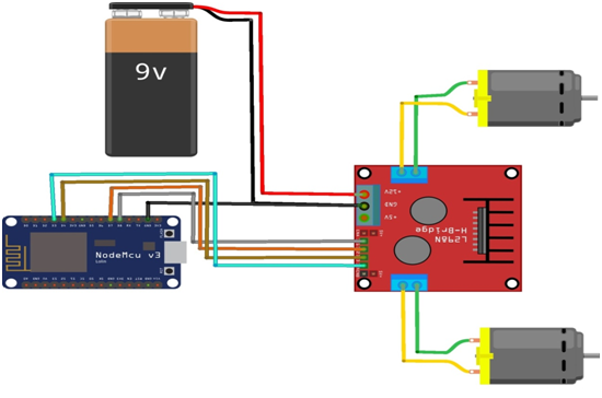
  2. Connect the 5V Battery to the L293D Motor Driver.
  3. Connect the micro motor M1,M2 pins to the L293D Motor Driver M3 & the second micro motor M1,M2 pins to the L293D Motor Driver M4 respectively .
  4. Connect the Arduino Mega board pins 5V, gnd to the voltage converter V IN, gnd properly.
  5. Connect the Voltage converter V Out, gnd pins to the micro motor gnd, vcc pins & the second micro motor gnd, vcc pins properly.
  6. Connect the micro motor C1,C2 pins to the Arduino Mega board pins 18,19 & the second micro motor C1,C2 pins to the Arduino Mega board pins 20,21 respectively.
  7. Check the Circuit Connections.
  8. Check the Arduino program.
  9. Run the Arduino program.

Arduino Program

#include <AFMotor.h>
#include <Encoder.h>
AF_DCMotor motor1(4);
AF_DCMotor motor2(3);
Encoder myEnc1(21,20);
Encoder myEnc2(18,19);
long oldPosition1  = -999;
long oldPosition2  = -999;
long m1Pos = 0;
long m1Dir = 0;
long m2Pos = 0;
long m2Dir = 0;
long md1=2000;
long md2=2000;

void setup()
{
  Serial.begin(9600);
  Serial.println("Motor test!");
  
  motor1.setSpeed(200);
  motor2.setSpeed(200);
  motor1.run(RELEASE);
  motor2.run(RELEASE);
  motor1Move(md1,0);
  motor2Move(md2,0);
}

void loop()
{
  checkMotor1();
  checkMotor2();
  delay(5);
}

void motor1Move(int d1,int d2)
{
  m1Pos=d1;
  m1Dir = d2;
  if (d2==0)
  {
    motor1.run(FORWARD);
  }
  else if (d2==1)
  {
    motor1.run(BACKWARD);
  }
}

void motor2Move(int d1,int d2)
{
  m2Pos=d1;
  m2Dir = d2;
  if (d2==0)
  {
    motor2.run(FORWARD);
  }
  else if (d2==1)
  {
    motor2.run(BACKWARD);
  }
}

void checkMotor1()
{
  long newPosition1 = myEnc1.read();
  if (m1Dir==0)
  {
    if ( newPosition1>m1Pos)
    {
      m1Pos=0;
      motor1.run(RELEASE);
      myEnc1.write(0);
      motor1Move(md1,1);
    }
  }
  else
  {
    if ( abs(newPosition1)>m1Pos)
    {
      m1Pos=0;
      motor1.run(RELEASE);
      myEnc1.write(0);
      
      motor1Move(md1,0);
    }
  }
}

void checkMotor2()
{
  long newPosition2 = myEnc2.read();
  if (m2Dir==0)
  {
    if ( newPosition2>m2Pos)
    {
      m2Pos=0;
      motor2.run(RELEASE);
      myEnc2.write(0);
      motor2Move(md2,1);
    }
  }
  else
  {
    if ( abs(newPosition2)>m2Pos)
    {
      m2Pos=0;
      motor2.run(RELEASE);
      myEnc2.write(0);
      motor2Move(md2,0);
    }
  }
}

Arduino Tutorials – Lesson 30 – Sharp Distance IR Sensor Module (2Y0A02 F 5x) using ARDUINO UNO

Creating distance of the target object in the range of (20-150) cm detect program using Arduino UNO

Required Components

  1. Arduino Uno Board -1 no
  2. Sharp IR 2Y0A02 F 5x sensor -1 no
  3. Data Cable -1 no
  4. Jumper wires -3 no

Circuit

Steps

  1. Make sure the components are working properly.
  2. Connect Sharp distance Sensor board VCC, GND to 5V, GND of Arduino Uno Board.
  3. Connect Sharp IR 2Y0A02 F5x sensor Board data pin to the Arduino Uno Board A0 pin.
  4. Check the Arduino program.
  5. Check the Circuit Connections.
  6. Run the Arduino program.

Arduino Program

#include <SharpIR.h>
#define ir A0
#define model 20150
SharpIR SharpIR(ir, model);

void setup() 
{
  Serial.begin(9600);
}

void loop() 
{
  delay(2000);   
  unsigned long pepe1=millis();
  int dis=SharpIR.distance();  
  Serial.print("Mean distance: ");  
  Serial.println(dis);
  
  unsigned long pepe2=millis()-pepe1;  
  Serial.print("Time taken (ms): ");
  Serial.println(pepe2);
}  

Usage

  1. Touch-less switch (Sanitary equipment, Control of illumination, etc., )
  2. Sensor for energy saving (ATM, Copier, Vending machine, Laptop computer, LCD monitor)
  3. Amusement equipment (Robot, Arcade game machine)

Arduino Tutorials – Lesson 29 – Servo motor control by Ultrasonic Sensor Module using Arduino UNO

Creating Servo motor control by Ultrasonic sensor program using Arduino UNO

Required Components

  1. Ultrasonic sensor board -1 no
  2. Arduino Uno board -1 no
  3. Servo Motor -1 no
  4. Bread board -1 no
  5. Data Cable -1 no
  6. Connecting Wires -8 no

Circuit

Steps

  1. Make sure the components are working properly.
  2. Ultrasonic Sensor board, Servo motor VCC, GND connected to 5V, GND of Arduino Uno Board through breadboard.
  3. Connect Ultrasonic sensor Board echo, trigger pin to the Arduino Uno Board 2, 3 pin.
  4. Connect Servo motor data pin to Arduino Uno Board pin 5.
  5. Check the Arduino program.
  6. Check the Circuit Connections.
  7. Run the Arduino program.

Arduino Program

#include <Servo.h>
Servo myservo;
#define echoPin 2 
#define trigPin 3 
long duration; 
int distance; 
void setup() 
{
  pinMode(trigPin, OUTPUT);
  pinMode(echoPin, INPUT);
  myservo.attach(5); 
  Serial.begin(9600);
  Serial.println("Ultrasonic Sensor HC-SR04 Test"); 
  Serial.println("with Arduino UNO R3");
  myservo.write(0);
}
void loop() 
{
  digitalWrite(trigPin, LOW);
  delayMicroseconds(2);
  digitalWrite(trigPin, HIGH);
  delayMicroseconds(10);
  digitalWrite(trigPin, LOW);
  duration = pulseIn(echoPin, HIGH);
  distance = duration * 0.034 / 2;  
  Serial.print("Distance: ");
  Serial.print(distance);
  Serial.println(" cm");
  
  if(distance<=40)
  {
    myservo.write(0);
  }
  else
  {
    myservo.write(160);
  }
}

Usage

  1. Robotic sensing
  2. Dustbin open and close

Arduino Tutorials – Lesson 28 – Node MCU

Creating an LED control from web browser program

Required Components

  1. Node MCU Board -1 no
  2. Bread Board -1 no
  3. Data Cable -1 no
  4. LED -1 no

Circuit

Steps

  1. Make sure the components are working properly.
  2. Connect Node MCU Board to the Bread Board.
  3. Connect the LED Anode(+) pin to Node MCU D7(13) and cathode(-)pin to Gnd.
  4. Check the Arduino program.
  5. Check the Circuit Connections.
  6. Run the Arduino program.

Arduino Program

#include <ESP8266WiFi.h>
const char* ssid = "******";
const char* password = "********";
int ledPin = 13; // GPIO13
WiFiServer server(80);

void setup() 
{
  Serial.begin(115200);
  delay(10);
  pinMode(ledPin, OUTPUT);
  digitalWrite(ledPin, LOW);
  Serial.println();
  Serial.println();
  Serial.print("Connecting to ");
  Serial.println(ssid);
  WiFi.begin(ssid, password);
  
  while (WiFi.status() != WL_CONNECTED) 
  {
    delay(500);
    Serial.print(".");
  }
  Serial.println("");
  Serial.println("WiFi connected");
  server.begin();
  Serial.println("Server started");
  Serial.print("Use this URL to connect: ");
  Serial.print("http://");
  Serial.print(WiFi.localIP());
  Serial.println("/");
}

void loop() 
{
  WiFiClient client = server.available();
  if (!client) 
  {
    return;
  }
  Serial.println("new client");
  while(!client.available()){
    delay(1);
  }
  String request = client.readStringUntil('\r');
  Serial.println(request);
  client.flush();
  int value = LOW;
  if (request.indexOf("/LED=ON") != -1)  {
    digitalWrite(ledPin, HIGH);
    value = HIGH;
  }
  if (request.indexOf("/LED=OFF") != -1)  {
    digitalWrite(ledPin, LOW);
    value = LOW;
  }
  client.println("HTTP/1.1 200 OK");
  client.println("Content-Type: text/html");
  client.println(""); //  do not forget this one
  client.println("<!DOCTYPE HTML>");
  client.println("<html>");
  client.print("Led pin is now: ");
  
  if(value == HIGH) {
    client.print("On");
  } 
  else {
    client.print("Off");
  }
  client.println("<br><br>");
  client.println("<a href=\"/LED=ON\"\"><button>Turn On </button></a>");
  client.println("<a href=\"/LED=OFF\"\"><button>Turn Off </button></a><br/>");
  client.println("</html>");
  delay(1);
  Serial.println("Client disonnected");
  Serial.println("");
}

Usage

  1. Prototyping of  IoT devices
  2. Low power battery operated applications
  3. Network

Arduino Tutorials – Lesson 27 – Position Encoder sensor using Arduino MEGA2560

Creating position encoder sensor direction change program using Arduino MEGA2560

Required Components

  1. Position encoder sensor -1 no
  2. Arduino board Mega 2560 -1 no
  3. Connecting Wires -4 no

Circuit

Steps

  1. Make sure the components are working properly.
  2. Connect the position encoder sensor to the Arduino Mega 2560.
  3. Connect the Arduino pin 6&7 to Position encoder sensor CLK & DT pin .
  4. Connect the +5v and ground(gnd) connections respectively.
  5. Check the Arduino program.
  6. Check the Circuit Connections.
  7. Run the Arduino program.

Arduino Program

#define outputA 8
#define outputB 9
int counter = 0;
int aState;
int aLastState;

void setup() 
{
  pinMode (outputA,INPUT);
  pinMode (outputB,INPUT);
  Serial.begin (9600);
  aLastState = digitalRead(outputA);
}

void loop() 
{
  aState = digitalRead(outputA); // Reads the "current" state of the outputA
  if (aState != aLastState)
  {
    if (digitalRead(outputB) != aState) {
      counter ++;
    } 
    else {
      counter --;
    }
    Serial.print("Position: ");
    Serial.println(counter);
  }
  aLastState = aState;
}

Usage

  1. Automation
  2. Aerospace
  3. Textiles

Arduino Tutorials – Lesson 26 – Accelerometer sensor with servo motor control using Arduino UNO

Creating accelerometer sensor program using Arduino UNO

Required Components

  1. Accelerometer sensor (MPU 6050) -1 no
  2. Arduino UNO board -1 no
  3. Jumper cable -4 no
  4. Servo motor -1 no

Circuit

Steps

  1. Make sure the components are working properly.
  2. Connect the Arduino UNO pin SDA & SCL to accelerometer sensor SDA & SCL pin.
  3. Connect the servo motor data pin to the Arduino UNO pin 2.
  4. Connect the +5v and ground connections respectively.
  5. Check the Arduino program.
  6. Check the Circuit Connections.
  7. Run the Arduino program.

Arduino Program

#include <Wire.h>
#include <MPU6050.h>
#include <Servo.h>   
Servo sg90;          
int servo_pin = 2;
MPU6050 sensor ;
int16_t ax, ay, az ;
int16_t gx, gy, gz ;

void setup ()
{ 
  sg90.attach ( servo_pin );
  Wire.begin ( );
  Serial.begin  (9600); 
  Serial.println  ( "Initializing the sensor" ); 
  
  sensor.initialize ( ); 
  Serial.println (sensor.testConnection ( ) ? "Successfully Connected" : "Connection failed"); 
  delay (1000); 
  Serial.println ( "Taking Values from the sensor" );
  delay (1000);
}

void loop () 
{ 
  sensor.getMotion6 (&ax, &ay, &az, &gx, &gy, &gz);
  ax = map (ax, -17000, 17000, 0, 180) ;
  Serial.println (ax);
  sg90.write (ax); 
  delay (200);
}

Usage

  1. Mobile phones
  2. Drone camera stabilization
  3. To detect faults in rotator machine
  4. To display images in an upright position on screens of digital cameras

Arduino Tutorials – Lesson 25 – L298N Motor Driver Module using Arduino UNO

Creating 4 DC motors or 2 DC motors with directional and speed control program using Arduino UNO

Required Components

  1. L298N Motor Driver Module -1 no
  2. Arduino UNO -1 no
  3. DC Motor(gear) -2 no
  4. 12V Battery -1 no
  5. Data Cable -1 no
  6. Connecting Wires -4 no

Circuit

Steps

  1. Make sure the components are working properly.
  2. Connect the 12V Battery to the L298N Motor Driver.
  3. Connect the ENA, IN1, IN2, IN3, IN4, ENB pins to the Arduino UNO board pins 4, 2, 3,5, 6, 7 properly.
  4. Connect the DC motor pins to the motor driver output pins.
  5. Connect the ground connection respectively.
  6. Check the Circuit Connections.
  7. Check the Arduino program.
  8. Run the Arduino program.

Arduino Program

int motor1pin1 = 2;
int motor1pin2 = 3;
int enPin1 = 4;

int motor2pin1 = 5;
int motor2pin2 = 6;
int enPin2 = 7;


void setup() 
{
  pinMode(motor1pin1, OUTPUT);
  pinMode(motor1pin2, OUTPUT);
  pinMode(enPin1, OUTPUT);
  digitalWrite(enPin1, HIGH);
  
  pinMode(motor2pin1, OUTPUT);
  pinMode(motor2pin2, OUTPUT);
  pinMode(enPin2, OUTPUT);
  digitalWrite(enPin2, HIGH);
}

void loop() 
{
  digitalWrite(motor1pin1, HIGH);
  digitalWrite(motor1pin2, LOW);
  digitalWrite(motor2pin1, HIGH);
  digitalWrite(motor2pin2, LOW);
  delay(1000);
  
  digitalWrite(motor1pin1, LOW);
  digitalWrite(motor1pin2, HIGH);
  digitalWrite(motor2pin1, LOW);
  digitalWrite(motor2pin2, HIGH);
  delay(1000);
}

Usage

  1. Drive DC motors.
  2. Drive Stepping motors.
  3. In Robotics.