To control 2 DC motors with directional and speed control
Required Components
L298N Motor Driver Module_1 no
Raspberry Pi Pico_1 no
DC Motor(gear)_2 no
12V Battery_1 no
Data Cable_1 no
Connecting Wires_4 no
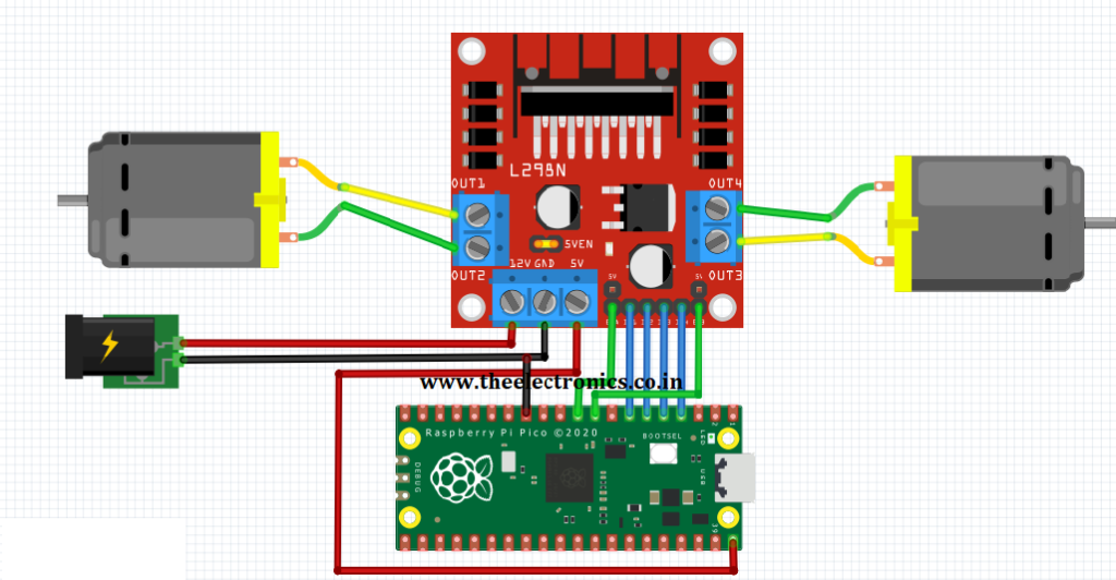
Circuit
Steps
Make sure the components are working properly.
Connect the 12V Battery to the L298N Motor Driver.
Connect the ENA, IN1, IN2, IN3, IN4, ENB pins to the Raspberry Pi Pico board pins GP7, GP5, GP4, GP3, GP2, GP6 properly.
Connect the DC motor pins to the motor driver output pins.
Connect the ground connection respectively.
Check the Electrical Circuit.
Check the Python program.
Run the Python program.
Python Program
from machine import Pin
import utime

m1 = Pin(5, Pin.OUT)
m2 = Pin(4, Pin.OUT)
m3 = Pin(3, Pin.OUT)
m4 = Pin(2, Pin.OUT)

en1 = Pin(6, Pin.OUT)
en2 = Pin(7, Pin.OUT)

en1(1)  # motor 1 enable, set value 0 to disable
en2(1)  # motor 2 enable, set value 0 to disable

while True:
    #Both Motor in forward direction
    m1(1)
    m2(0)
    m3(1)
    m4(0)
    utime.sleep(1)
    #Both Motor in Reverse direction
    m1(0)
    m2(1)
    m3(0)
    m4(1)
    utime.sleep(1)
    #Both Motor in stop position
    m1(0)
    m2(0)
    m3(0)
    m4(0)
    utime.sleep(5)
To control 1 DC motor with directional and speed control
Required Components
L298N Motor Driver Module_1 no
Raspberry Pi Pico_1 no
DC Motor(gear)_1 no
12V Battery_1 no
Data Cable_1 no
Connecting Wires_4 no
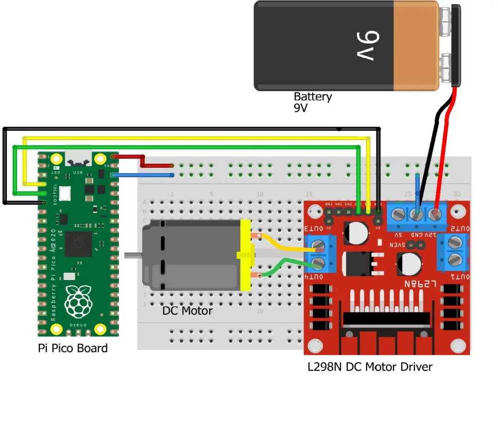
Circuit
Steps
Make sure the components are working properly.
Connect the 12V Battery to the L298N Motor Driver.
Connect the ENA, IN1, IN2 pins to the Raspberry Pi Pico board pins GP4, GP2, GP3 properly.
Connect the DC motor pins to the motor driver output pins.
Connect the ground connection respectively.
Check the Electrical Circuit.
Check the Python program.
Run the Python program.
Python Program
from machine import Pin
import utime

m1 = Pin(2, Pin.OUT)
m2 = Pin(3, Pin.OUT)

en1 = Pin(4, Pin.OUT)

en1(1)  # motor 1 enable, set value 0 to disable

while True:
    #Both Motor in forward direction
    m1(1)
    m2(0)
    utime.sleep(1)
    #Both Motor in Reverse direction
    m1(0)
    m2(1)
    utime.sleep(1)
    #Both Motor in stop position
    m1(0)
    m2(0)
    utime.sleep(5)
To control 4×4 Matrix Keypad Module using Raspberry Pi Pico
Required Components
4×4 Matrix Keypad_1 no
Raspberry Pi Pico board_1 no
Data Cable_1 no
Connecting Wires_8 no
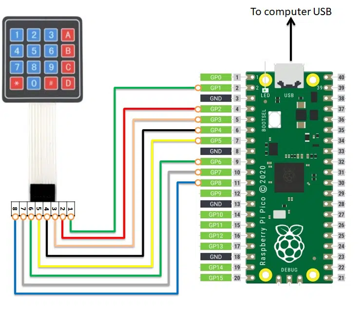
Circuit
Steps
Make sure the components are working properly.
4×4 Matrix keypad 1 to 8 pins connected to GP1 to GP8 of Raspberry Pi Pico Board respectively.
Check the Python program.
Check the Electrical Circuit.
Run the Python program.
Python Program
from machine import Pin
import utime

# define PINs according to cabling
# following array matches 1,2,3,4 PINs from 4x4 Keypad Matrix
col_list=[1,2,3,4]
# following array matches 5,6,7,8 PINs from 4x4 Keypad Matrix
row_list=[5,6,7,8]

# set row pins to output and change array elements from
#    int to Pin objects, all set to high
for x in range(0,4):
    row_list[x]=Pin(row_list[x], Pin.OUT)
    row_list[x].value(1)

# set columns pins to input and change array elements
#   from int to Pin objects. We'll read user input here
for x in range(0,4):
    col_list[x] = Pin(col_list[x], Pin.IN, Pin.PULL_UP)

# Create a map between keypad buttons and chars
key_map=[["D","#","0","*"],\
         ["C","9","8","7"],\
         ["B","6","5","4"],\
         ["A","3","2","1"]]

def Keypad4x4Read(cols,rows):
  for r in rows:
    r.value(0)
    result=[cols[0].value(),cols[1].value(),cols[2].value(),cols[3].value()]
    if min(result)==0:
      key=key_map[int(rows.index(r))][int(result.index(0))]
      r.value(1) # manages key keept pressed
      return(key)
    r.value(1)

# Start the main loop
print("--- Ready to get user inputs ---")
while True:
    key=Keypad4x4Read(col_list, row_list)
    if key != None:
      print("You pressed: "+key)
      utime.sleep(0.3) # gives user enoght time to release without having double inputs
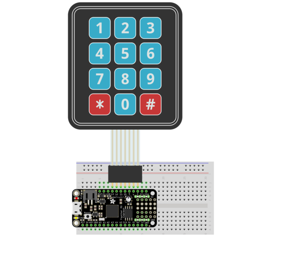
To control 4×3 Matrix Keypad Module using Raspberry Pi Pico
Required Components
4×3 Matrix Keypad_1 no
Raspberry Pi Pico board_1 no
Data Cable_1 no
Connecting Wires_8 no
Circuit
Steps
Make sure the components are working properly.
4×3 Matrix keypad 1 to 7 pins connected to GP1 to GP7 of Raspberry Pi Pico Board respectively.
Check the Python program.
Check the Electrical Circuit.
Run the Python program.
Python Program
from machine import Pin
import utime

# define PINs according to cabling
# following array matches 1,2,3 PINs from 3x4 Keypad Matrix
col_list=[1,2,3]
# following array matches 4,5,6,7 PINs from 3x4 Keypad Matrix
row_list=[4,5,6,7]

# set row pins to output and change array elements from
#    int to Pin objects, all set to high
for x in range(0,4):
    row_list[x]=Pin(row_list[x], Pin.OUT)
    row_list[x].value(1)

# set columns pins to input and change array elements
#   from int to Pin objects. We'll read user input here
for x in range(0,3):
    col_list[x] = Pin(col_list[x], Pin.IN, Pin.PULL_UP)

# Create a map between keypad buttons and chars
key_map=[["#","0","*"],\
         ["9","8","7"],\
         ["6","5","4"],\
         ["3","2","1"]]

def Keypad3x4Read(cols,rows):
  for r in rows:
    r.value(0)
    result=[cols[0].value(),cols[1].value(),cols[2].value()]
    if min(result)==0:
      key=key_map[int(rows.index(r))][int(result.index(0))]
      r.value(1) # manages key keept pressed
      return(key)
    r.value(1)

# Start the main loop
print("--- Ready to get user inputs ---")
while True:
    key=Keypad3x4Read(col_list, row_list)
    if key != None:
      print("You pressed: "+key)
      utime.sleep(0.3) # gives user enoght time to release without having double inputs