Ball collecting robot is a mobile controlled wheeled robot which can be used to collect balls in a playing area. This is a prototype project which will be useful to learn about mobile robots. This concept can be extended to build fully functional ball collecting robot.
Component Required
Arduino Nano
Bluetooth
12V DC Motors (2)
Dc Motor Driver
12V battery
Servo Motor
Cables & Wires
Robot Wheels
Robot Gripper
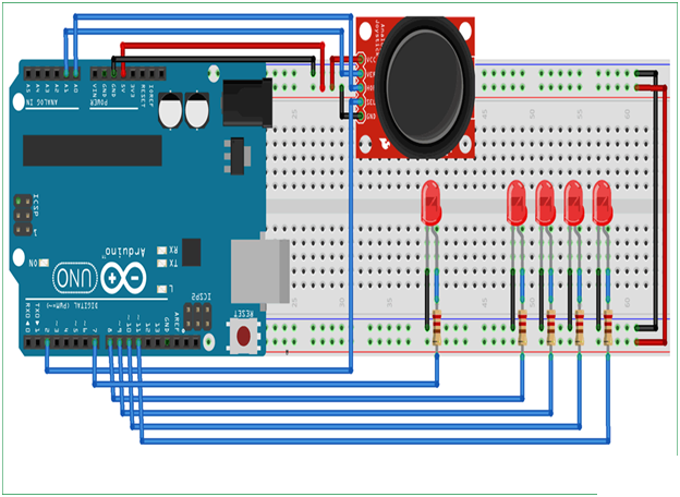
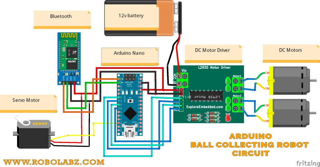
Circuit Diagram
Steps
1 :Connect the DC Motors with DC Motor Drive
2: Connect the DC motor drive OUTPUT Pins with Arduino Nano Pins
   Drive Pins                Arduino Nano

      1A                        D3
      1B                        D4
      2A                        D5
      2B                        D6
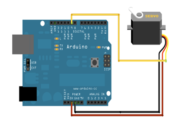
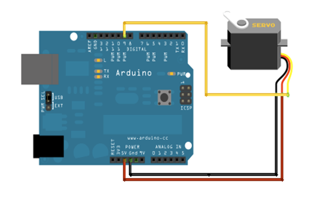
3: Connect the Servo Motor with Arduino Nano
      wires                  Pins

       Red                    5V
       Black                  GND
       Yellow                 D10
4 : Connect the Bluetooth with Arduino Nano
  Bluetooth               Arduino Nano

   5V                          5V
   GND                         GND
   RX                          TX
   TX                          RX
5 : Check the Connection once
6 : Upload the arduino program
7 : Install the mobile application in the mobile device.
8: Test the robot with mobile application
Arduino Program
#include <AFMotor.h>
#include <Servo.h>
// Check the motor driver datasheet for motor pin connections
AF_DCMotor rm(1, MOTOR12_64KHZ);  // Right motor
AF_DCMotor lm(4, MOTOR34_64KHZ);  // Left motor
Servo grServo; // Servo motor for gripper
byte incomingByte ;

void setup()
{
   Serial.begin(9600);
  // Set motors speed
   rm.setSpeed(200);
   lm.setSpeed(200);
   rm.run(RELEASE);
   lm.run(RELEASE);
	grServo.attach(10); // Attach gripper
}
void loop()
{
   if (Serial.available() > 0) {
    incomingByte = Serial.read(); // Read the input character from bluetooth serial input buffer

    if (incomingByte == 'A')
    {
         grServo.write(120);      // Gripper Open Position
    }
    else if (incomingByte =='B')
    {
        grServo.write(180);      // Gripper Close Position
    }
    else if (incomingByte == 'C')
    {
        rm.run(FORWARD);        // Run both motors in forward direction
        lm.run(FORWARD);
    }
    else if (incomingByte == 'D')
    {
        rm.run(BACKWARD);       // Run both motors in backward direction
        lm.run(BACKWARD);
    }
    else if (incomingByte == 'E')
    {
        rm.run(BACKWARD);       // Turning Left. Run right motor in backward direction and left motor in forward direction
        lm.run(FORWARD);
    }
    else if (incomingByte == 'G')
    {
        rm.run(FORWARD);        // Turning Right. Run right motor in forward direction and left motor in backward direction
        lm.run(BACKWARD);
    }
    else if (incomingByte == 'F')
    {
        rm.run(RELEASE);        // Stop both motors
        lm.run(RELEASE);
    }
   }
   delay(20);
}