Python Tutorials – Lesson 6 – Position Encoder sensor using Raspberry Pi Pico
To get the reading of position encoder sensor direction change using Raspberry Pi Pico
Required Components
Position encoder sensor_1 no
Raspberry Pi Pico_1 no
Connecting Wires_4 set
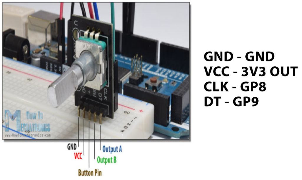
Circuit
Steps
Make sure the components are working properly.
Connect the position encoder sensor to the Raspberry Pi Pico.
Connect the Raspberry Pi Pico pin GP8 & GP9 to Position encoder sensor CLK & DT pin and Position encoder SW pin to the GP2 of Raspberry Pi Pico.
Connect the +5v and ground(gnd) connections respectively.
Check the Python program.
Check the Electrical Circuit.
Run the Python program.
Python Program
from machine import Pin
import utime

DT_Pin = Pin(9, Pin.IN, Pin.PULL_UP)
CLK_Pin = Pin(8, Pin.IN, Pin.PULL_UP)
SW = Pin(2, Pin.IN, Pin.PULL_UP)

LEDs = [25,4]

#create an empty list to assing pins in pico
led_pins = []

for x in range(0,2):
    led_pins.append(Pin(LEDs[x], Pin.OUT))

value = 0
previousValue = 1

def rotary_changed():

    global previousValue
    global value

    if previousValue != CLK_Pin.value():
        if CLK_Pin.value() == 0:
            if DT_Pin.value() == 0:

                value = (value - 1)%2
                print("anti-clockwise", value)
            else:

                value = (value + 1)%2
                print("clockwise", value)
        previousValue = CLK_Pin.value()

    if SW.value() == 0:
        print("Button pressed")
        utime.sleep(1)

while True:
    for i in range(0,2):
        led_pins[i].value(0)
        rotary_changed()
        led_pins[value].value(1)
        utime.sleep(0.001)