Python Tutorials – Lesson 5 – Sweep Servo Motor Control Using Raspberry Pi Pico

To test servo motor using Raspberry Pi Pico

Required Components

  1. Servo motor (5V) _ 1 no
  2. Raspberry Pi Pico board _ 1 no
  3. Connecting wires _ 1 set

Circuit

Steps

  1. Make sure the components are working properly.
  2. Connect Raspberry Pi Pico board VBus and GND pin to the servo motor by using wires.
  3. Connect servo motor data pin to the Raspberry Pi Pico pin GP15.
  4. Check the Python program.
  5. Check the circuit connections.
  6. Run the Python program.

Python Program

from machine import Pin,PWM
import utime

MID = 1500000
MIN = 1000000
MAX = 2000000

led = Pin(25,Pin.OUT)
pwm = PWM(Pin(15))

pwm.freq(50)
pwm.duty_ns(MID)

while True:
    pwm.duty_ns(MIN)
    utime.sleep(1)
    pwm.duty_ns(MID)
    utime.sleep(1)
    pwm.duty_ns(MAX)
    utime.sleep(1)

Python Tutorials – Lesson 4 –Single LED Control With Single Pushbutton

To check single LED blink using push button

Required Components

  1. LED _ 1 no
  2. 220 Ω Resistor_ 1 no
  3. 10 K Ω Resistor _1 no
  4. Pushbutton _1 no
  5. Bread Board _1 no
  6. Raspberry Pi Pico _1 no
  7. Connecting wires _1 Set

Circuit

Steps

  1. Make sure the components are working properly.
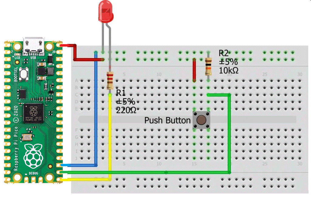
  2. Connect Raspberry Pi Pico board VBus and GND pin to the bread board by using wires.
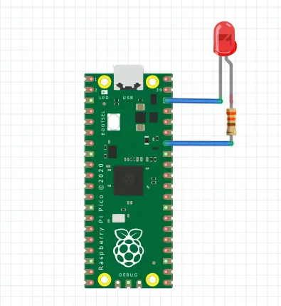
  3. Connect 220 Ω Resistor to the LED Anode (+) pin and LED cathode (-) pin to Gnd.
  4. Connect 220 Ω Resistor another pin to GP16.
  5. Connect 10 k Ω Resistor to the switch button.
  6. Connect switch button another pin to the Raspberry Pi Pico pin GP17.
  7. When we press the push button LED blinks.
  8. Check the Python program.
  9. Check the circuit connections.
  10. Run the Python program.

Python Program

from machine import Pin
from time import sleep
led_pin = Pin(16, Pin.OUT)    # 16 number in is Output
push_button = Pin(17, Pin.IN)  # 17 number pin is input

while True:
  
  logic_state = push_button.value()
  if logic_state == True:     # if push_button pressed
      led_pin.value(1)             # led will turn ON
  else:                       # if push_button not pressed
      led_pin.value(0)    

Python Tutorials – Lesson 3 – Use A Buzzer Module Using Raspberry Pi Pico

To control Buzzer using Raspberry Pi Pico

Required Components

  1. Buzzer module _ 1 no
  2. Raspberry Pi Pico _ 1 no
  3. Connecting wires _ 1 set

Circuit

Steps

  1. Make sure the components are working properly.
  2. Connect the Raspberry Pi Pico board GP15th pin to the Buzzer.
  3. Connect Buzzer board GND to GND of Raspberry Pi Pico Board.
  4. Check the Electrical Circuit.
  5. Check the Python program.
  6. Run the Python program.

Python Program

from machine import Pin, PWM
from utime import sleep
buzzer = PWM(Pin(15))

tones = {
"B0": 31,
"C1": 33,
"CS1": 35,
"D1": 37,
"DS1": 39,
"E1": 41,
"F1": 44,
"FS1": 46,
"G1": 49,
"GS1": 52,
"A1": 55,
"AS1": 58,
"B1": 62,
"C2": 65,
"CS2": 69,
"D2": 73,
"DS2": 78,
"E2": 82,
"F2": 87,
"FS2": 93,
"G2": 98,
"GS2": 104,
"A2": 110,
"AS2": 117,
"B2": 123,
"C3": 131,
"CS3": 139,
"D3": 147,
"DS3": 156,
"E3": 165,
"F3": 175,
"FS3": 185,
"G3": 196,
"GS3": 208,
"A3": 220,
"AS3": 233,
"B3": 247,
"C4": 262,
"CS4": 277,
"D4": 294,
"DS4": 311,
"E4": 330,
"F4": 349,
"FS4": 370,
"G4": 392,
"GS4": 415,
"A4": 440,
"AS4": 466,
"B4": 494,
"C5": 523,
"CS5": 554,
"D5": 587,
"DS5": 622,
"E5": 659,
"F5": 698,
"FS5": 740,
"G5": 784,
"GS5": 831,
"A5": 880,
"AS5": 932,
"B5": 988,
"C6": 1047,
"CS6": 1109,
"D6": 1175,
"DS6": 1245,
"E6": 1319,
"F6": 1397,
"FS6": 1480,
"G6": 1568,
"GS6": 1661,
"A6": 1760,
"AS6": 1865,
"B6": 1976,
"C7": 2093,
"CS7": 2217,
"D7": 2349,
"DS7": 2489,
"E7": 2637,
"F7": 2794,
"FS7": 2960,
"G7": 3136,
"GS7": 3322,
"A7": 3520,
"AS7": 3729,
"B7": 3951,
"C8": 4186,
"CS8": 4435,
"D8": 4699,
"DS8": 4978
}

song = ["E5","G5","A5","P","E5","G5","B5","A5","P","E5","G5","A5","P","G5","E5"]
#song = ["G4","A4","C5","F5","D5","F5","G5","F5","D5","C5","A4","C5","D5","F5","G5","G5","G5","A5","G5","G5","F5"]
#song = ["B4","B4","B4","C5","C5","C5","F5","F5","G5","F5","D5","C5","C5","B4"]


def playtone(frequency):
    buzzer.duty_u16(5000)
    buzzer.freq(frequency)

def bequiet():
    buzzer.duty_u16(0)

def playsong(mysong):
    for i in range(len(mysong)):
        if (mysong[i] == "P"):
            bequiet()
        else:
            playtone(tones[mysong[i]])
        sleep(0.3)
    bequiet()
playsong(song)

Python Tutorials – Lesson 2 – Double led blink using Raspberry Pi Pico

To check double LED blink using Raspberry Pi Pico

Required Components

  1. Led _ 2 no
  2. Raspberry Pi Pico board _ 1 no
  3. Connecting wires _ 1 set

Circuit

Steps

  1. Make sure the components are working properly.
  2. Connect Led GND pins to Raspberry Pi Pico GND pins respectively.
  3. Connect Raspberry Pi Pico GP2, GP20 pins to the each LED anode pin.
  4. Check the Python program.
  5. Check the circuit connections.
  6. Run the Python program.

Python Program

from machine import Pin
import utime  #timer

led1=Pin(2,Pin.OUT)
led2=Pin(17,Pin.OUT)

while(True):    
    led1.value(1)
    led2.value(1)
    utime.sleep(2) #delay of 1 sec
    led1.value(0)
    led2.value(0)
    utime.sleep(2)

Python Tutorials – Lesson 1 – Single LED Blink Using Raspberry Pi Pico

To check single LED blink using Raspberry Pi Pico

Required Components

  1. Led _1 no
  2. Resister 330Ω _1 no
  3. Raspberry Pi Pico board _1 no
  4. Connecting wires _1 set

Circuit

Steps

  1. Make sure the components are working properly.
  2. Connect 330 Ω Resistor to the LED Anode (+) pin and LED cathode (-) pin to Gnd.
  3. Connect Raspberry Pi Pico pin 28 to the LED anode pin.
  4. Check the Python program.
  5. Check the circuit connections.
  6. Run the Python program.

Python Program

from machine import Pin
import utime  #timer

led1=Pin(2,Pin.OUT)

while(True):    
    led1.value(1)
    utime.sleep(2) #delay of 1 sec
    led1.value(0)
    utime.sleep(2)

Arduino Tutorials – Lesson 47 – Vibration Sensor on Raspberry Pi Pico

To control Vibration Sensor using Raspberry Pi Pico

Required Components

  1. Vibration Sensor (SW 18010p)_1 no
  2. Raspberry Pi Pico_1 no
  3. Connecting wires_1 set

Circuit

Steps

  1. Make sure the components are working properly.
  2. Connect the Vibration Sensor to the Raspberry Pi Pico board.
  3. Connect the Raspberry Pi Pico board GP14th pin to the Vibration Sensor D0 Pin.
  4. Connect Vibration Sensor board VCC, GND to 3V3 (OUT), GND of Raspberry Pi Pico Board.
  5. Check the Electrical Circuit.
  6. Check the Arduino program.
  7. Run the Arduino program.

Arduino Program

int LED_Pin = 25;
int vibr_Pin = 14;

void setup()
{
  pinMode(LED_Pin, OUTPUT);
  pinMode(vibr_Pin, INPUT); 
  Serial.begin(9600); 
}

void loop()
{
  long measurement =TP_init();
  delay(50);
  Serial.println(measurement);
  if (measurement > 1000)
  {
    digitalWrite(LED_Pin, HIGH);
  }
  else
  {
    digitalWrite(LED_Pin, LOW); 
  }
}

long TP_init()
{
  delay(10);
  long measurement=pulseIn (vibr_Pin, HIGH);  
  return measurement;
}

Arduino Tutorials – Lesson 46 – L298N Motor Driver Module control double DC Motor using Raspberry Pi Pico

To control up to 2 DC motors with directional and speed control

Required Components

  1. L298N Motor Driver Module_1 no
  2. Raspberry Pi Pico_1 no
  3. DC Motor(gear)_2 no
  4. 12V Battery_1 no
  5. Data Cable_1 no
  6. Connecting Wires_4 no

Circuit

Steps

  1. Make sure the components are working properly.
  2. Connect the 12V Battery to the L298N Motor Driver.
  3. Connect the ENA, IN1, IN2, IN3, IN4, ENB pins to the Raspberry Pi Pico board pins GP7, GP5, GP4, GP3, GP2, GP6 properly.
  4. Connect the DC motor pins to the motor driver output pins.
  5. Connect the ground connection respectively.
  6. Check the Electrical Circuit.
  7. Check the Arduino program.
  8. Run the Arduino program.

Arduino Program

int motor1pin1 = 2;
int motor1pin2 = 3;
int enPin1 = 4;

int motor2pin1 = 5;
int motor2pin2 = 6;
int enPin2 = 7;


void setup()
 {
  pinMode(motor1pin1, OUTPUT);
  pinMode(motor1pin2, OUTPUT);
  pinMode(enPin1, OUTPUT);
  digitalWrite(enPin1, HIGH);

  pinMode(motor2pin1, OUTPUT);
  pinMode(motor2pin2, OUTPUT);
  pinMode(enPin2, OUTPUT);
  digitalWrite(enPin2, HIGH);

}

void loop() 
{
  digitalWrite(motor1pin1, HIGH);
  digitalWrite(motor1pin2, LOW);
  digitalWrite(motor2pin1, HIGH);
  digitalWrite(motor2pin2, LOW);
  delay(1000);

  digitalWrite(motor1pin1, LOW);
  digitalWrite(motor1pin2, HIGH);
  digitalWrite(motor2pin1, LOW);
  digitalWrite(motor2pin2, HIGH);
  delay(1000);
}

Arduino Tutorials – Lesson 45 – L298N Motor Driver Module control single DC Motor using Raspberry Pi Pico

To control DC motor with directional and speed control using Raspberry Pi Pico

Required Components

  1. L298N Motor Driver Module_1 no
  2. Raspberry Pi Pico_1 no
  3. DC Motor(gear)_1 no
  4. 12V Battery_1 no
  5. Data Cable_1 no
  6. Connecting Wires_4 no

Circuit

Steps

  1. Make sure the components are working properly.
  2. Connect the 12V Battery to the L298N Motor Driver.
  3. Connect the ENA, IN1, IN2 pins to the Raspberry Pi Pico board pins GP4, GP2, GP3 properly.
  4. Connect the DC motor pins to the motor driver output pins.
  5. Connect the ground connection respectively.
  6. Check the Electrical Circuit.
  7. Check the Arduino program.
  8. Run the Arduino program.

Arduino Program

int motor1pin1 = 2;
int motor1pin2 = 3;
int enPin1 = 4;

void setup() 
{
 pinMode(motor1pin1, OUTPUT);
 pinMode(motor1pin2, OUTPUT);
 pinMode(enPin1, OUTPUT);
 digitalWrite(enPin1, HIGH);
}

void loop() 
{
 digitalWrite(motor1pin1, HIGH);
 digitalWrite(motor1pin2, LOW);
 delay(1000);

 digitalWrite(motor1pin1, LOW);
 digitalWrite(motor1pin2, HIGH);
 delay(1000);
}

Arduino Tutorials – Lesson 44 – Ultrasonic Sensor Module using Raspberry Pi Pico

To control Ultrasonic sensor using Raspberry Pi Pico

Required Components

  1. Ultrasonic sensor board_1 no
  2. Raspberry Pi Pico board_1 no
  3. Data Cable_1 no
  4. Connecting Wires_8 no

Circuit

Steps

  1. Make sure the components are working properly.
  2. Ultrasonic Sensor board VCC, GND connected to VBus, GND of Raspberry Pi Pico Board.
  3. Connect Ultrasonic sensor Board echo, trigger pin to the Raspberry Pi Pico Board GP15, GP14 pin.
  4. Check the Arduino program.
  5. Check the Electrical Circuit.
  6. Run the Arduino program.

Arduino Program

#define echoPin 15 
#define trigPin 14 
long duration; 
int distance; 

void setup() 
{
  pinMode(trigPin, OUTPUT); 
  pinMode(echoPin, INPUT); 
  Serial.begin(9600); 
  Serial.println("Ultrasonic Sensor HC-SR04 Test");
  Serial.println("with Arduino UNO R3");
}
void loop() 
{
  digitalWrite(trigPin, LOW);
  delayMicroseconds(2);
  
  digitalWrite(trigPin, HIGH);
  delayMicroseconds(10);
  digitalWrite(trigPin, LOW);
  
  duration = pulseIn(echoPin, HIGH);
  
  distance = duration * 0.034 / 2; 
  
  Serial.print("Distance: ");
  Serial.print(distance);
  Serial.println(" cm");
  delay(500);
} 

Arduino Tutorials – Lesson 43 – Humidity Sensor on Raspberry Pi Pico

To control Humidity Sensor using Raspberry Pi Pico

Required Components

  1. Humidity Sensor (DHT11)_1 no
  2. Raspberry Pi Pico Board_1 no
  3. Connecting wires_1 set

Circuit

Steps

  1. Make sure the components are working properly.
  2. Connect the Raspberry Pi Pico board GP16th pin to the Humidity Sensor.
  3. Connect Humidity Sensor board VCC, GND to 3V3 (OUT), GND of Raspberry Pi Pico Board.
  4. Check the Electrical Cicuit.
  5. Check the Arduino program.
  6. Run the Arduino program.

Arduino Program

#include "DHT.h"
#define DHTPIN 16
#define DHTTYPE DHT11
DHT dht(DHTPIN, DHTTYPE);

void setup() 
{
  Serial.begin(9600);
  Serial.println("DHTxx test!");
  dht.begin();
}

void loop( )
{
  delay(2000);
  float h = dht.readHumidity();
  float t = dht.readTemperature();
  float f = dht.readTemperature(true);
  
  if (isnan(h) || isnan(t) || isnan(f)) 
  {
    Serial.println("Failed to read from DHT sensor!");
    return;
  }  
  Serial.print ("Humidity: ");
  Serial.print (h);
  Serial.println (" %\t");
  Serial.print ("Temperature: ");
  Serial.print (t);
  Serial.println (" *C ");
  Serial.print (f);
  Serial.println (" *F\t");
}