Arduino Tutorials – Lesson 8 – LDR Sensor on Arduino UNO

Creating LDR Sensor program using Arduino UNO

Required Components

  1. LED -1 no
  2. LDR -1 no
  3. Resistor 10K Ω -1 no
  4. Resistor 220 Ω -1 no
  5. Bread board -1 no
  6. Arduino UNO board -1 no
  7. Connecting cables -1 set

Circuit

Steps

  1. Make sure the components are working properly.
  2. Connect the Arduino UNO A0 pin to the LDR.
  3. Connect the Arduino UNO 13th pin to the LED.
  4. Connect the Arduino Uno 5V, GND to the LDR Sensor using jumper wires.
  5. Check the Arduino program.
  6. Check the circuit connections.
  7. Run the Arduino program.

Arduino Program

const int ledPin=13;
const int ldrPin=A0;

void setup(  )
{
  Serial.begin(9600);
  pinMode (ledPin,OUTPUT);
  pinMode (ldrPin,INPUT);
}

void loop( )
{
  int ldrstatus = analogRead(ldrPin);
  if (ldrstatus<=300)
  {
    digitalWrite(ledPin,HIGH);
    Serial.print("LDR in Dark,LED is ON");
  }
  else
  {
    digitalWrite(ledPin,LOW);
    Serial.print ("LDR in Light,LED Is Off");
  }
}

Usage

  1. Alarm clocks
  2. Street lights
  3. Light intensity meters
  4. Burglar alarm circuits

Projects

  1. Shooting game

Arduino Tutorials – Lesson 7 – Three LEDs Connect With A Single Switch Blink Using Arduino UNO

Creating three LEDs blink program using push button

Required Components

  1. Led -3 no
  2. Resistor(220 ohm) -3 no
  3. Resistor(10K) -1 no
  4. Pushbutton -1 no
  5. Bread Board -1 no
  6. Arduino UNO -1 no
  7. Connecting Wires -1 set
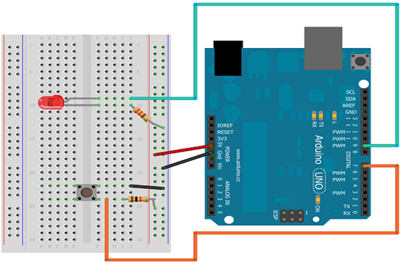
Circuit

Steps

  1. Make sure the components are working properly.
  2. Connect Arduino board 5V and GND pin to the bread board by using wires.
  3. Connect 220 Ω Resistors to each LED Anode (+) pin and all cathode (-) pin to Gnd.
  4. Connect Arduino pin 9, 10, 11 to the 220 Ω Resistors another pin.
  5. Connect 10 k Ω Resistor to the switch.
  6. Connect switch button another pin to the Arduino pin 8.
  7. When we press the push button 1st time LED1 blinks.
  8. When we press the push button 2nd time LED1 off and LED2 blinks.
  9. When we press the push button 3rd time LED2 off and LED3 blinks.
  10. Repeated last 3steps as per the program.
  11. Check the Arduino program.
  12. Check the circuit connections.
  13. Run the Arduino program.

Arduino Program

int led1=9;
int led2=10;
int led3=11;
int btn=0;
const int buttonpin=8;

void setup (  )
{
  pinMode (led1, OUTPUT);
  pinMode (led2, OUTPUT);
  pinMode (led3, OUTPUT);

  pinMode (buttonpin, INPUT);
  Serial.begin(9600);
}

void loop (  )
{
  
  if (digitalRead(buttonpin)== HIGH)
  {
    btn ++;
    Serial.println(btn);
    Lighton(btn);
    delay (500);
  }
  if (btn >=3)
  {
    btn=0;     
  }
}

void  Lighton(int n)
{
  digitalWrite (led1, LOW);
  digitalWrite (led2, LOW);
  digitalWrite (led3, LOW);
  if (n==1){
    digitalWrite (led1, HIGH);
  }
  else if (n==2)
  {
    digitalWrite (led2, HIGH);
  }
  else if (n==3)
  {
    digitalWrite (led3, HIGH);     
  } 
}

Usage

  1. Advertising application.
  2. Decoration purposes.

Arduino Tutorials – Lesson 6 – Single LED Control With Single Pushbutton

Creating single LED blink program using push button

Required Components

  1. LED -1 no
  2. 220 Ω Resistor -1 no
  3. 10 KΩ Resistor -1 no
  4. Push button -1 no
  5. Bread Board -1 no
  6. Arduino Board -1 no
  7. Connecting wires -1 Set

Circuit

Steps

  1. Make sure the components are working properly.
  2. Connect Arduino board 5v and GND pin to the bread board by using wires.
  3. Connect 220 Ω Resistor to the LED Anode (+) pin and cathode (-) pin to Gnd.
  4. Connect 220 Ω Resistor another pin to Arduino pin 9.
  5. Connect 10 k Ω Resistor to the switch button.
  6. Connect switch button another pin to the Arduino pin 7.
  7. When we press the push button LED blinks.
  8. Check the Arduino program.
  9. Check the circuit connections.
  10. Run the Arduino program.

Arduino Program

int ledPin = 9;
int buttonPin = 7;

void setup()
{
  pinMode(ledPin, OUTPUT);
  pinMode(buttonPin, INPUT);
}


void loop()
{  
  int button = digitalRead(buttonPin);
  if (button==HIGH)
  {
    digitalWrite(ledPin,HIGH);
  } 
  else
  {
    digitalWrite(ledPin, LOW);
  }
}

Usage

  1. Switching operations.

Arduino Tutorials – Lesson 5- Servo Motor Angle Setup Using Arduino UNO

Creating servo motor angle program using Arduino UNO

Required Components

  1. Servo motor(5V) -1 no
  2. Arduino board -1 no
  3. Connecting wires -1 set

Circuit

Steps

  1. Make sure the components are working properly.
  2. Connect Arduino board 5v and GND pin to the servo motor 5v and GND by using wires.
  3. Connect servo motor data pin to the Arduino UNO pin 9.
  4. Write Arduino code to run motor which angle changes from +90 degree to -90 degree.
  5. Check the Arduino program.
  6. Check the circuit connections.
  7. Run the Arduino program.

Arduino Program

#include <Servo.h>
Servo myservo;
int pos=0;
int stepdelay=10;

void setup(  )
{
  myservo.attach(9);
}

void loop(  )
{
  moveFromTo(0,90);
  delay (1000);
  moveFromTo(90,180);
  delay(1000);
  moveFromTo(180,90);
  delay (1000);
  moveFromTo(90,0);
  delay (1000);
}

void moveFromTo(int From, int To)
{
  if (From <=To)
  {
    for (pos=From; pos <=To; pos +=1)
    {
      myservo.write(pos);
      delay( stepdelay);
    }
  }
  else
  {
    for(pos=From; pos >=To;pos -=1)
    {
      myservo.write(pos);
      delay( stepdelay);
    }
  }
}

Usage

  1. Conveyor Belts.
  2. Camera Auto Focus.
  3. Solar Tracking System.
  4. Metal Cutting & Metal Forming Machines.
  5. Antenna Positioning.
  6. Printing Presses/Printers.

Projects

  1. Robot-Arm.
  2. Sensor dustbin.