Arduino Tutorials – Lesson 45 – L298N Motor Driver Module control single DC Motor using Raspberry Pi Pico

To control DC motor with directional and speed control using Raspberry Pi Pico

Required Components

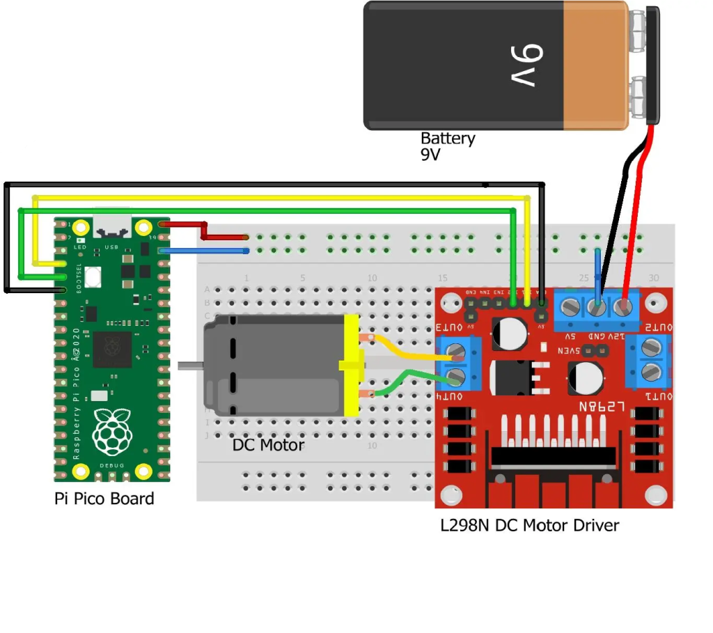
  1. L298N Motor Driver Module_1 no
  2. Raspberry Pi Pico_1 no
  3. DC Motor(gear)_1 no
  4. 12V Battery_1 no
  5. Data Cable_1 no
  6. Connecting Wires_4 no

Circuit

Steps

  1. Make sure the components are working properly.
  2. Connect the 12V Battery to the L298N Motor Driver.
  3. Connect the ENA, IN1, IN2 pins to the Raspberry Pi Pico board pins GP4, GP2, GP3 properly.
  4. Connect the DC motor pins to the motor driver output pins.
  5. Connect the ground connection respectively.
  6. Check the Electrical Circuit.
  7. Check the Arduino program.
  8. Run the Arduino program.

Arduino Program

int motor1pin1 = 2;
int motor1pin2 = 3;
int enPin1 = 4;

void setup() 
{
 pinMode(motor1pin1, OUTPUT);
 pinMode(motor1pin2, OUTPUT);
 pinMode(enPin1, OUTPUT);
 digitalWrite(enPin1, HIGH);
}

void loop() 
{
 digitalWrite(motor1pin1, HIGH);
 digitalWrite(motor1pin2, LOW);
 delay(1000);

 digitalWrite(motor1pin1, LOW);
 digitalWrite(motor1pin2, HIGH);
 delay(1000);
}

Arduino Tutorials – Lesson 44 – Ultrasonic Sensor Module using Raspberry Pi Pico

To control Ultrasonic sensor using Raspberry Pi Pico

Required Components

  1. Ultrasonic sensor board_1 no
  2. Raspberry Pi Pico board_1 no
  3. Data Cable_1 no
  4. Connecting Wires_8 no

Circuit

Steps

  1. Make sure the components are working properly.
  2. Ultrasonic Sensor board VCC, GND connected to VBus, GND of Raspberry Pi Pico Board.
  3. Connect Ultrasonic sensor Board echo, trigger pin to the Raspberry Pi Pico Board GP15, GP14 pin.
  4. Check the Arduino program.
  5. Check the Electrical Circuit.
  6. Run the Arduino program.

Arduino Program

#define echoPin 15 
#define trigPin 14 
long duration; 
int distance; 

void setup() 
{
  pinMode(trigPin, OUTPUT); 
  pinMode(echoPin, INPUT); 
  Serial.begin(9600); 
  Serial.println("Ultrasonic Sensor HC-SR04 Test");
  Serial.println("with Arduino UNO R3");
}
void loop() 
{
  digitalWrite(trigPin, LOW);
  delayMicroseconds(2);
  
  digitalWrite(trigPin, HIGH);
  delayMicroseconds(10);
  digitalWrite(trigPin, LOW);
  
  duration = pulseIn(echoPin, HIGH);
  
  distance = duration * 0.034 / 2; 
  
  Serial.print("Distance: ");
  Serial.print(distance);
  Serial.println(" cm");
  delay(500);
} 

Arduino Tutorials – Lesson 43 – Humidity Sensor on Raspberry Pi Pico

To control Humidity Sensor using Raspberry Pi Pico

Required Components

  1. Humidity Sensor (DHT11)_1 no
  2. Raspberry Pi Pico Board_1 no
  3. Connecting wires_1 set

Circuit

Steps

  1. Make sure the components are working properly.
  2. Connect the Raspberry Pi Pico board GP16th pin to the Humidity Sensor.
  3. Connect Humidity Sensor board VCC, GND to 3V3 (OUT), GND of Raspberry Pi Pico Board.
  4. Check the Electrical Cicuit.
  5. Check the Arduino program.
  6. Run the Arduino program.

Arduino Program

#include "DHT.h"
#define DHTPIN 16
#define DHTTYPE DHT11
DHT dht(DHTPIN, DHTTYPE);

void setup() 
{
  Serial.begin(9600);
  Serial.println("DHTxx test!");
  dht.begin();
}

void loop( )
{
  delay(2000);
  float h = dht.readHumidity();
  float t = dht.readTemperature();
  float f = dht.readTemperature(true);
  
  if (isnan(h) || isnan(t) || isnan(f)) 
  {
    Serial.println("Failed to read from DHT sensor!");
    return;
  }  
  Serial.print ("Humidity: ");
  Serial.print (h);
  Serial.println (" %\t");
  Serial.print ("Temperature: ");
  Serial.print (t);
  Serial.println (" *C ");
  Serial.print (f);
  Serial.println (" *F\t");
}

Arduino Tutorials – Lesson 42 – LDR Sensor on Raspberry Pi Pico

To control LDR Sensor using Raspberry Pi Pico Board

Required Components

  1. LDR Sensor_1 no
  2. Raspberry Pi Pico board_1 no
  3. Connecting wires_1 set

Circuit

Steps

  1. Make sure the components are working properly.
  2. Connect the Raspberry Pi Pico GP27 pin to the LDR D0 pin.
  3. Connect the Raspberry Pi Pico 3V3 (OUT) pin to the LDR +5V pin.
  4. Connect the Raspberry Pi Pico GND to the LDR GND pin.
  5. Check the Arduino program.
  6. Check the Electrical circuit.
  7. Run the Arduino program.

Arduino Program

const int ledPin=25;
const int ldrPin=27;

void setup(  )
{
  Serial.begin(9600);
  pinMode (ledPin,OUTPUT);
  pinMode (ldrPin,INPUT);
}

void loop( )
{
  int ldrstatus = analogRead(ldrPin);
  if (ldrstatus<=300)
 {
    digitalWrite(ledPin,HIGH);
    Serial.print("LDR in Dark,LED is ON");
  }
  else
  {
    digitalWrite(ledPin,LOW);
    Serial.print ("LDR in Light,LED Is Off");
  }
}

Arduino Tutorials – Lesson 41 – Position Encoder sensor using Raspberry Pi Pico

To get the reading of position encoder sensor direction change using Raspberry Pi Pico

Required Components

  1. Position encoder sensor_1 no
  2. Raspberry Pi Pico_1 no
  3. Connecting Wires_4 set

Circuit

Steps

  1. Make sure the components are working properly.
  2. Connect the position encoder sensor CLK pin to the Raspberry Pi Pico GP8.
  3. Connect the position encoder sensor DT pin to the Raspberry Pi Pico GP9.
  4. Connect the +5v and ground(gnd) connections respectively.
  5. Check the Arduino program.
  6. Check the Electrical Circuit.
  7. Run the Arduino program.

Arduino Program

#define outputA 8
#define outputB 9
int counter = 0;
int aState;
int aLastState;

void setup() 
{
 pinMode (outputA,INPUT);
 pinMode (outputB,INPUT);
 Serial.begin (9600);
 aLastState = digitalRead(outputA);
}

void loop() 
{
 aState = digitalRead(outputA); // Reads the "current" state of the outputA
 if (aState != aLastState)
{
  if (digitalRead(outputB) != aState)
 {
   counter ++;
  } else {
  counter --;
  }
  Serial.print("Position: ");
  Serial.println(counter);
 }
 aLastState = aState;
}

Arduino Tutorials – Lesson 40 – Sweep Servo Motor Control Using Raspberry Pi Pico

To test servo motor using Raspberry Pi Pico

Required Components

  1. Servo motor (5V) _ 1 no
  2. Raspberry Pi Pico board _ 1 no
  3. Connecting wires _ 1 set

Circuit

Steps

  1. Make sure the components are working properly.
  2. Connect Raspberry Pi Pico board VBus and GND pin to the servo motor by using wires.
  3. Connect servo motor data pin to the Raspberry Pi Pico pin GP15.
  4. Check the Arduino program.
  5. Check the circuit connections.
  6. Run the Arduino program.

Arduino Program

#include<Servo.h>
Servo servo1;

void setup(  )
{
  servo1.attach(15);
}

void loop(  )
{
  servo1.write(0);
  delay(1000);
  servo1.write(90);
  delay(1000);
  servo1.write(180);
  delay(1000);
}

Arduino Tutorials – Lesson 39 – Single LED Control With Single Pushbutton

To check single LED blink using push button

Required Components

  1. LED _ 1 no
  2. 220 Ω Resistor_ 1 no
  3. 10 K Ω Resistor _1 no
  4. Pushbutton _1 no
  5. Bread Board _1 no
  6. Raspberry Pi Pico _1 no
  7. Connecting wires _1 Set

Circuit

Steps

  1. Make sure the components are working properly.
  2. Connect Raspberry Pi Pico board VBus and GND pin to the bread board by using wires.
  3. Connect 220 Ω Resistor to the LED Anode (+) pin and cathode (-) pin to Gnd.
  4. Connect 220 Ω Resistor another pin to GP16.
  5. Connect 10 k Ω Resistor to the switch button.
  6. Connect switch button another pin to the Raspberry Pi Pico pin GP17.
  7. When we press the push button LED blinks.
  8. Check the Arduino program.
  9. Check the circuit connections.
  10. Run the Arduino program.

Arduino Program

int ledPin = 16;
int buttonPin = 17;

void setup()
{
  pinMode(ledPin, OUTPUT);
  pinMode(buttonPin, INPUT);
}


void loop()
{  
  int button = digitalRead(buttonPin);
  if (button==HIGH)
  {
    digitalWrite(ledPin,HIGH);
  } 
  else
  {
    digitalWrite(ledPin, LOW);
   }
}

Arduino Tutorials – Lesson 38 – Use A Buzzer Module Using Raspberry Pi Pico

To control Buzzer using Raspberry Pi Pico

Required Components

  1. Buzzer module _ 1 no
  2. Raspberry Pi Pico _ 1 no
  3. Connecting wires _ 1 set

Circuit

Steps

  1. Make sure the components are working properly.
  2. Connect the Raspberry Pi Pico board GP15th pin to the Buzzer.
  3. Connect Buzzer board GND to GND of Raspberry Pi Pico Board.
  4. Check the Electrical Circuit.
  5. Check the Arduino program.
  6. Run the Arduino program.

Arduino Program

const int buzzer = 15;

void setup( )
{
  pinMode(buzzer, OUTPUT);
}

void loop()
{
  tone(buzzer, 1000);
  delay(1000);
  noTone(buzzer);
  delay(1000);        
}

Arduino Tutorials – Lesson 37 – Double led blink using Raspberry Pi Pico

To check double LED blink using Raspberry Pi Pico

Required Components

  1. Led _ 2 no
  2. Raspberry Pi Pico board _ 1 no
  3. Connecting wires _ 1 set

Circuit

Steps

  1. Make sure the components are working properly.
  2. Connect Led GND pins to Raspberry Pi Pico GND pins respectively.
  3. Connect Raspberry Pi Pico GP2, GP20 pins to the each LED anode pins.
  4. Check the Arduino program.
  5. Check the circuit connections.
  6. Run the Arduino program.

Arduino Program

int Led1 = 2;
int Led2 = 20;

void setup() 
{
  pinMode(Led1, OUTPUT);
  pinMode(Led2, OUTPUT);

}

void loop() 
{
  digitalWrite(Led1, HIGH);
  digitalWrite(Led2, HIGH);
  delay(1000);

  digitalWrite(Led1, LOW);
  digitalWrite(Led2, LOW);
  delay(1000);
}

Arduino Tutorials – Lesson 36 – Single LED Blink Using Raspberry Pi Pico

To check single LED blink using Raspberry Pi Pico.

Required Components

  1. Led _1 no
  2. Resister 330Ω _1 no
  3. Raspberry Pi Pico board _1 no
  4. Connecting wires _1 set

Circuit

Steps

  1. Make sure the components are working properly.
  2. Connect 330 Ω Resistor to the LED Anode (+) pin and LED cathode (-) pin to Gnd.
  3. Connect Raspberry Pi Pico pin 28 to the LED anode pin.
  4. Check the Arduino program.
  5. Check the circuit connections.
  6. Run the Arduino program.

Arduino Program

int led1 = 28;

void setup ( )
{
  pinMode (led1, OUTPUT);
}

void loop ( )
{
  digitalWrite (led1, HIGH);
  delay (3000);
  digitalWrite (led1, LOW);
  delay (1000);
}